
Charging an Electric Car · 20 April 07
Most of the time when someone considers converting a car to electric the last thing that probably springs to mind is the charger. The car itself garners the most attention since it’s the biggest and most visible aspect of an EV, followed by the motor. Somewhere down the list, after the batteries or controller, the charger choice lies.
Batteries are all but useless (or will soon be rendered so) without a good charger. Everything else in an electric car is there to use the batteries, with little thought to their well being (and that often includes the driver). It’s the charger that gets tasked with taking care of and getting the most out of the batteries. Without a good charger you could easily reduce battery life by 50%, which is kind of an expensive on-going design flaw.
There are a number of approaches to charging batteries, from do-it-yourself “bad boy” chargers to computer controlled, high voltage fast chargers. Before we start talking about the different approaches let’s take a bit of a detour and cover some basic electronics to get everyone on the same page. (click here to skip to the charging info)
Ohm’s Law
To your charger a battery is just a resistor. A simplified schematic might look like:

Power source (charger) on the left, resistive load (battery) on the right. In a simple circuit like this the amount of voltage and resistance determine how much current flows. Let’s say we have 14 volts “E“ and the resistor “R“ is 10 ohms. OHM’s law states that current “I“ is:
I = E/R
I = 14/10
I = 1.4 amps
1.4 amps of current flowing through the circuit. Increase the voltage or decrease the resistance and current flow goes up, increase the resistance or decrease the voltage and there’s less current flowing through the circuit.
The difference between a resistor and a battery is that the battery is also power source, as well as having internal resistance. In order to charge the battery we’ll need to apply a voltage that is higher than the battery’s. You can illustrate this by measuring the voltage across your car battery when it is hooked up to a 12v charger.
Let’s think about batteries as a bunch of resistors again, just to illustrate a few more concepts. Whenever you combine resistors there are two configurations you might see: either parallel or series.
Series Circuits
An EV battery pack is usually in series so let’s discuss that first. Resistors in series add up. So if the resistors R1 through R4 were all 10 ohms each the total resistance would be 40 ohms. Using our earlier equation:
I = 14/40
I = 0.35 amps
We get a current flow of 0.35, significantly less than with the previous circuit. We’d have to increase the voltage to 56 volts to see the same 1.4 amps of current we saw when using a single 10 ohm resistor.
A good thing to remember about a series circuit is that the current is the same through each resistor. If we are feeding the circuit 1.4 amps at 56 volts, then we know each resistor has 1.4 amps flowing through it. On the other hand the voltage varies across each resistor. Let’s say our power supply is putting out 56 volts at 1.4 amps. To figure out the voltage across each resistor you use the formula:
E = I * R
E = 1.4 * 10
E = 14
The voltage across each resistor is 14 and if we add them all up we get back to our total applied voltage of 56 volts. Cool! The resistors don’t all have to be the same value, which in the case of batteries they probably seldom are, but the formula works just the same.
So in a series circuit the current is the same throughout, but the voltage is different across each resistor.
Parallel Circuits
Another configuration you might see is a parallel circuit, where the resistors are parallel with each other. Right off the bat you might notice that every resistor is tied to the power supply: therefore they must all have the same voltage applied to them. True, and that means the current flowing through each resistor and how the resistors combine is going to be different from a series circuit.
Let’s stick with R1-R4 being 10 ohms each, just to keep the math straightforward. The total resistance formula for parallel circuits is a bit messier:
Rtotal = 1/ (1/R1 + 1/R2 + 1/R3 + 1/R4)
Rtotal = 1/ (1/10 + 1/10 + 1/10 + 1/10)
Rtotal = 2.5 ohms
If you are a math wiz you’ll probably notice that if all of the resistors are the same you can just use a shortcut of:
Rtotal = Resistance/# of resistors
Rtotal = 10 / 4
Rtotal = 2.5
When resistors are added in series the total resistance goes UP and in parallel it goes DOWN. Less resistance means our parallel circuit is allowing more current through:
I = 14 / 2.5
I = 5.6 amps
Woo hoo, look at all of that current! It’s a little deceptive though: unlike a series circuit the current through each resistor when in parallel is not the same, it’s cumulative. Remember each resistor is 10 ohms and each resistor is hooked straight to the power supply, so the only thing that CAN change in our formula is current:
I = 14 / 10
I = 1.4 amps (across a single resistor)
Current in a parallel circuit is cumulative, so you add up the current flowing through each resistor to get the total:
I = 1.4 + 1.4 + 1.4 + 1.4
I = 5.6
Series-Parallel Circuits
Finally there are series-parallel circuits. Dr. Larry’s EV is a good illustration of this arrangement as his battery layout looks like:
At this point our heads explode into a thousand pieces (all having a specific ohms value, of course)! But, if we divide and conquer it’s not too bad. Again we’ll assume each resistor is 10 ohms
First off we figure out what the combined resistance of a parallel “leg” is (i.e. R1 & R2 are a “leg”):
R = 10 / 2
R = 5 ohms
Then add up each of these six legs for total resistance and figure out the current from the supply:
Rtotal = 5 + 5 + 5 + 5 + 5 + 5
Rtotal = 30 ohms
I = 14 / 30
I = 0.47 amps
Now, armed with the total current flow in the circuit we can figure out each leg’s voltage drop:
E = 0.47 amps * 5 ohms
E = 2.33 volts (per leg)
I = 2.33 / 10 (to get current per resistor in leg)
I = 0.23 amps
So even though we have 14 volts and 0.47 amps coming out of the charger, each resistor is only going to be seeing 2.3 volts and 0.23 amps.
Now Dr. Larry doesn’t suffer from one single power supply trying to feed the entire pack, instead he has a dedicated 12v power supply hooked to each leg (i.e. R1 & R2, R3 & R4). Using these formulas we know that if the charger is capable of supplying 8amps maximum, that the most each battery will see is 4amps.
One of the nice things about having batteries in parallel is when the car wants 100 amps, each battery in a leg only has to supply 50 amps (assuming they are the same type of battery), so there’s less wear and tear on an individual battery. On the other hand it can be tricky to monitor each leg for a bad battery. A pair of batteries is only as strong as the weakest one.
Those are some of the basics behind what happens when you hook up resistors (or batteries) in parallel or series. If you think of the batteries in these terms it can help to visualize how things work electrically, especially when you start adding a charger to the circuit.
How Much Charger Do You Need?
Our 120vac Zivan (144vdc output) charger delivered up to 8 amps and could charge the pack in 3-6 hours, depending on how far we’d driven. A 240vac Bycan charger we had for a while could deliver almost 20 amps and charge the pack in half the time. But, if you are charging at the end of the day and have all night to do so is it worth springing the extra $$‘s to speed it up?
How much amperage will you need out of your charger? It depends on how much power your EV uses each day and how fast you want it recharged. Let’s say we use 36 amp hours in one day of driving. For reference, 36Ah is equivalent to pulling 36 amps for a full hour, or 72 amps for half an hour, or 216 amps over a ten minute period. However you do it the Ah meter will say 36Ah.
And however you use the power the charger has to replenish it … and some. Remember, whenever you move energy from one place to another or from one form to another, you inevitably lose some along the way. The heat you feel on the charger, wires and batteries during a charge is all lost energy. Simply stated this means we’ll need to put more than 36Ah back in to bring the batteries to full charge.
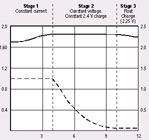
Let’s pick a number and say it’ll take 40Ah to top the batteries off. You’d think an 8 amp charger would take about five hours to do this, but in actuality it may be six or more. Check out a typical charging curve chart to see the suggested charge cycle for a lead-acid battery. As this site so nicely puts it, the charger has three key functions (which they cover in detail):
- Getting the charge into the battery (Charging)
- Optimising the charging rate (Stabilising)
- Knowing when to stop (Terminating)
I’d add that on top of doing all of this a good charger is also taking care of:
- shutting down if batteries overheat
- establish limits; both in voltage/current and TIME
- ability to run conditioning charges (for lead acid)
The second point is something I’m very familiar with. Let’s say the charger is at the first phase (constant current) of charging and is waiting for the battery pack to reach a certain threshold voltage so it can switch to the second phase, a slower, constant voltage top-off. What happens if the pack never reaches the cut-over voltage? We once awoke in the middle of the night to our CO2 detector beeping and found the charger essentially boiling the battery pack. Why? One (or two) of the battery cells had gone bad enough such that the phase one threshold voltage was never reached. Without a default timeout the charger merrily cranked eight amps into the pack.
This is one of the downsides of a full-pack charger. Without additional monitoring equipment or control it really has just a rough idea how things are going: as far as it is concerned you only have “one” big battery. There are ways around this of course, which we’ll talk about later.
All of these features, both safety and performance, start pushing the cost of a charger higher and higher. Considering that the EV market is quite small we don’t benefit from the price reductions of mass-produced products. Instead you get a few folks pouring their heart and soul into making a quality charger in the hopes that they’ll make a small profit along the way.
Types of Chargers

Bad Boy Charger
Eventually you’ll read about “Bad Boy Chargers” (BBc for short) so we’ll get that one out of the way first. There’s a few approaches to this, but the basic concept is to more or less plug your battery pack into the AC outlet … with a few diodes and a variac (variable transformer) tossed in for good measure. Some folks even use a FUSE! ":^)
When the charger died on my first EV I put together my own BBc after spending a couple of days trying to charge the pack one battery at a time with two cheap 12v chargers. It works, but is more in the category of a hand-grenades as far as finesse goes.
The main issue with this type of charger (and I don’t think anyone with something more expensive than flooded lead-acid batteries would dare use one) is that there’s no automatic control or regulation. You need to manually monitor the pack and as the batteries fill up adjust the charging level. No safety circuits and no fancy formulas, just brute force.
For reference there’s a few designs here and a more well-mannered BBc here.
Automotive Chargers
The next step up in price, functionality, and safety is to use a bunch of individual 12v automotive-style chargers. Dr. Larry uses this approach with his 72v EV. His EV has six chargers (and I think a 7th for the acc battery), one for each battery pair, and from what he’s told us they are doing a great job.
Some things to take into consideration when using this approach:
- charger outputs must be isolated from input AC and Ground
- depending on how many you use there may be:
- large start-up current surge, which could trip the breaker
- heavy AC load during charging: be careful to properly size extension cords and power strips
- may not be waterproof and/or do well in a jostling, dirty environment
- more parts, more things to go wrong
- ensure the charger doesn’t DRAIN your battery when it is off
On the plus side each of your batteries gets individual care and attention, assuming that the charger you are using is of good quality and matched to the type of battery you are charging.
An off-the-shelf *mart charger isn’t the only way to approach this either. There’s a few companies that make “ganged” chargers, in dual, triple, ten and other configurations (and various current outputs).
You’ll notice that as the current output goes up, so does the price.
EV Chargers
Next to the sticker shock of buying the motor and controller for an EV I suspect most converters get a lump in the throat when they start pricing out chargers. Admittedly so, like the motor it is a big investment. One thing that may help to deaden the pain a bit is that it’s a long term investment. When your current EV body rusts out or you outgrow it, it is a simple matter to pull the motor, controller, and charger out of the old vehicle and pop them into the new one.
You could probably do this for decades, especially since the controller and charger have no moving parts. And, if you’ve purchased a quality charger, it should be able to be reprogrammed to handle new types of batteries (although check before you buy, especially if you are leaning towards a certain battery type).
A few of the EV specific chargers on the market these days include: Manzanita Micro, Russco, and Zivan. There have been others, like the Bycan and K&W, but these are the ones I was able to find web pages for and seemed to be for sale.
The advantages of these types of systems is that A) they are engineered specifically for charging EV batteries, B) the companies are typically small and available for questions specific to EV systems, and C) they usually have a number of performance and safety features built in, along with additional options (temp probes, boosters, etc..).
The downside, somewhat, is that they see your battery pack as a whole and typically can’t monitor individual batteries. Although, to be fair, a twelve volt battery is composed of six cells and individual chargers can’t monitor each of these. But if we go down this path we’ll never make much headway in deciding on a charger!
Which leads us to …
Regulators
So far the choice has been lots of chargers (i.e. lots of points of failure/equipment) with tighter individual battery control vs. single dedicated EV chargers with fewer parts but less individual battery control.
Bypass regulators are small circuits that you hook to each battery in your pack as a companion to a single EV charger. Each regulator keeps an eye on its battery and automatically bypasses it when it senses a full charge. In that way you don’t have a bunch of batteries boiling away while one laggard takes its sweet time reaching full charge.
There’s been a few types out there over the years but it seems like the only ones currently in production are the Rudman regulators Mk II and Mk III, the later sporting a digital interface to talk to a smart charger. Lee Hart has posted a couple of designs for do-it-yourself regulators including a relatively simple zener-lamp regulator. And here’s a schematic of someone else’s clamper (pdf) (original here).
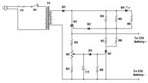
There’s one more from Lee, which I’ve linked to a couple times before: the TMSI Battery Balancer. It’s part battery charger, part monitor, and part regulator. And, because you build it yourself, it is extensible to do even more!
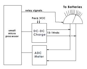
You’ll have to excuse the crude block diagram, it is by no means complete or accurate, but hopefully enough to explain the concept behind the design. Before you freak out, the thing in the upper right is supposed to look sort of like a rotary switch, with about twelve outputs. Yes, instead it looks like a bald guy with bad hair plugs!
Think of the relay signals line coming in from the CPU as a control signal which switches a virtual rotary switch (which in actuality is a big board of relays) such that one battery is hooked to the signal lines below; to the ADC (analog to digital converter) and DC-DC.
Once it has a battery hooked up there’s a pause to let things settle down and then the ADC (a digital voltmeter in this case) measures the voltage across the battery and sends the reading to the CPU. It repeats this for each battery in the pack and then the CPU picks the lowest reading of the bunch and goes back to that battery and turns on the small DC-DC converter to provide a “booster” charge to the battery.
So, unlike the regulators which bypass charged batteries this system goes around and tries to help out the weaker/slower batteries. You’ll still need a charger for the full pack, this unit merely “walks” around and helps things out. In addition to these functions it can also monitor a couple temperature probes, turn on LEDs, send signals out an RS-232 port for logging and/or a display on the dash.
The surprising feature is that it also performs the balancing while the system is discharging. It’s a little hard to wrap your head around at first, but basically it uses the full pack voltage, by way of the DC-DC converter, to help out a weaker battery, even though the battery is being used to help power your EV.
A number of folks have created their own chargers and regulators over the years. One that comes to mind is Peter’s BMS (which he’s redesigning). If you know of others post a link in the comments or send me an email. Same goes for any corrections or additions to the article.

Another great post!
A relatively new player to the market is Belktronix. http://belktronix.com/ (Web site needs a refreshed home page.)
The company sells DC EV systems including the following:
DC Motor Controller
Throttle Interface
Battery Monitors
Vehicle Integrator
Charging System +DC-DC Converter
I’ve not found any reviews for the complete system (I’ve seen positive ones for individual parts though) so may end up writing the 1st review, myself this year.
As always thanks for your informative site.
Manny
Hi, Jerry. At one time, JB Straubel offered a battery monitor, too. Don’t know if it is still available. the link is http://www.jstraubel.com/batbox/monitor.htm
Wow, another great chapter in Electronics for Dogs.
I have a MGB I would like to turn into a EV car. I’m looking into how I’m going to do it. This was a good start for what i’m getting into. Congradulations.
APM
I found this site and am going to order a charger for my Yugo.
http://quickcharge.com/contact1.htm
They have a 72 volt unit that is under $400.00.
Excellent post Jerry, I’ve learnt a lot reading this and will let others know about it.
It answers a lot of questions I had!
You have raised an excellent subject matter: Voltage clampers and chargers. May I offer my two cents’ opinions? Imo, the Zivan kills batteries, and there is an $8 voltage regulator/clamper that works. Check out the full story by googling for EV DIARY ROB MATTHIES, so far Part One to Part Seven have been posted. You’ll likely find useful information,
a 156 volt pack agm batts what is the volts at 50% dod ?
can you run the EV vehicle with the charger running, ie- as in having a generator on board?
Well, sure, but buying long enough extension cords can be quite cost prohibitive, not to mention unsafe to other drivers! :)
If what you are asking is “could I use the forward motion of the vehicle to charge the vehicle while I’m driving it” then, no, that’s against the law (of thermodynamics).
If what you are really asking is, “can I put a gas generator into the car and charge it while driving off the electric motor” then, yes, sure, but at that point it is no longer considered an electric car and is typically called a hybrid.
the third option is what i had in mind. yes i would like the option of having a hybrid car. we have a few short trips to make, but most of our trips are 50 to 150 miles round trip. i would like the option of continuous charging while on a longer trip. i did not know if the charger would work ok with the motor running. also i was wondering how to set up a system like that. i’m going to convert a 1995 s-10 pickup and have a warp 9 motor to go in it. i was thinking with a suplimental generator, sy 8000 watts, i could exspand my range without a lot of extra gasoline. what do you think. i’m sure someone else has already run the figuers on this.
Hi Josh,
Maybe a pusher EV will do the trick? Instead of adding all of the complication of a hybrid (generator, motor, control circuits) a pusher temporarily adds a gas motor to your EV for the times you need more range. Then the rest of the time when you are doing short commutes you leave the pusher at home: lighter car, less complexity. It also has the benefit of using an existing “car” is you get the existing emissions control too.
But, even if you decided to make your own hybrid (onboard motor/gen) you most likely wouldn’t use the charger. Chargers only supply 8 amps or so, even the beefy ones only do 20 amps and that’s with 240vac input. Going straight and steady down the road your EV might be sucking down 75 amps.
so, i would need 55000 plus watts from a generator to power my vehicle. no, i guess that would not be acceptable. i guess a beefy charger would not be able to extend my range much even if it ran all the time. i guess i was thinking if my wife and i went shopping 40 miles away, and left the generator running the whole trip we would have no problems getting around and getting back. (we live 40 miles from the nearest wal-mart, for example) i have a company truck that i run right now and my wife is self employed, so i’m still not decided on how much i can use a EV. but the mechanics of it are still very interesting to me. i work as a field service mechanic for Catapiller and my wife runs our side business. i’ve been a mechanic for 18 years now, mostly on large agricultural equipment. i do like to have a project to work on when i get home and i think building a EV is a great little project, if i can keep the cost down and the usefulness of the vehicle up.
I have a 1970 vw fastback with nine 8volt batteries powering a40 hp D&D motor series wound dc motor. when this pack expires I wan to run two 12v strings of 6 batteries it would only add about 190 lbs but In the interest of cost reduction I want to use the walmart marine batteries. What do you think of the dual string idea?
72 Volts is 72 Volts, the bigger question is the difference in Amps.
Two strings of batteries will double the amperage in comparison to just the one string but if the batteries are half the amperage to the nine 8 volt batteries then you haven’t gained anything other then weight.
http://www.angelfire.com/pa/baconbacon/page2.html
This link might help you decide how you want to go.
You might find that a string of 6volt batteries could be better for your needs.
(6+6+6+6+6+6+6+6+6+6+6+6)=72V through 12 batteries.
(8+8+8+8+8+8+8+8+8)=72V through 9 batteries.
((12+12+12+12+12+12) parallel (12+12+12+12+12+12)) = 72 Volts 12 batteries
You said that you have a “40HP” motor which first made me think of 746 watts = 1 HP which then lead to the formula Watts=Volts*Amps.
The more weight you add; the more amps the motor will draw when trying to perform the same task.
A basic charging question for anyone who can help:
I’ve read elsewhere that in the bulk charging phase, you can pretty much pump as much current into the batteries as you like (thus the BBc). At least until the voltage per cell reaches about 2.4v/cell.
Does the same hold true for voltage?
The reason I ask: I’ve got a 36v 20A charger, but a 48v (6v*8) pack. If I split the pack into two 24v strings, could I use the 36v charger for the bulk phase?
It would save time over the 5A charger I’ve been using.
Well, the current is a byproduct of the voltage and resistance. Let’s say, for simplicity sake, you have two 24volt batteries with an internal resistance of 2 ohms. If you put them in parallel you are halving the resistance to 1 ohm.
Of course battery resistance is more complicated than that and varies as a function of its charge and other factors. But if you think of it from the charger’s perspective it should make things a little easier.
So now you have a 36v charger across 24v batts and if it’s a good charger it will self-limit the current it puts out, in this case to 20 amps. It probably does this by varying a resistance in series with the charge (i.e. transistor/scr/something) and thus the voltage which is coming out. I’m not a charger expert by any means so take that all with a grain of salt.
Charger is cranking out 20 amps, batteries are sucking it down, and in time the batteries start feeling a little full and their voltage/resistance is higher and a steady charge current might tend to go down. But the charger is thinking, “hey, I gotta get these puppies up to 36volts. Let’s crank up the amps!” and it varies it’s internal resistance/voltage to maintain the 20 amps. Batteries start cooking.
Unattended you’d probably lose the batteries to overcharge. What you need to do is come up with a way to either adjust the charger to a lower voltage for 24v operation or to a higher one for 48v charging. One way to fake the charger into thinking it’s charging higher voltage batts is to put a resistor in series with the batteries. The charger is looking at voltage drop across its output, so the larger the resistance being “charged” the higher the voltage drop. Let’s say you added a 5 ohm resistor in series with the batteries. The charger would see 6 ohms total.
Remember a 36 volt charger probably really cranks out 40 volts or more in order to charge up a 36 volt pack. And the batteries themselves are changing resistance over the course of the charge, so this is where I get a little unsure about how best to choose a resistor. Oh, and the other kicker: the resistor has to be able to handle the maximum current going through the batteries. watts = volts * current so let’s say the max the charger can put out is 40 volts and 20 amps, which would be into a 2 ohm (or less) load. 1 ohm for batts, 1 ohm series resistor. P = i * i * r so our 1 ohm resistor needs to be able to handle at least 400 watts.
The idea here is that you’d design it for the lowest battery resistance (which will be pretty low) and then as the battery gets charged the charger will see a great voltage drop and lower its charging current, ultimately shutting off or dropping down to a safe trickle charge.
A quick search finds a 1 ohm 600 watt resistor for forty bucks. Maybe an incandescent light bulb might work instead (or a bunch of them). I think you might want to use a higher resistance too, even if it means sacrificing max current flow.
It’s early in the morning so I could be totally hallucinating all of this stuff. Double check with other folks, or maybe someone will jump into the comments and straighten me out if I’ve messed up.
I’m with Jerry, I think you’ll kill your batteries as soon as they get full. Even if you put a resistor in line to limit the current your batteries will go high resistance (for charging purposes) when they are full and they’ll take a larger part of the voltage and reduce that across the resistor. the sicker your batteries get, the more stress you will put them under with this (resistor) method. ‘Snot worth it.
Hrm… OK, thanks for the advice guys. Lots to consider.
Another option is hot-swappable packs! I’ve got 8 batteries in the car, but was given 20 batteries overall. I could put one pack on the slow (non-murderous) 24V charger while driving on the second pack, then swap ‘em.
OK, not practical.
You are on 48V right?
You could charge 36V and 12V and try to keep the levels matched. Move the 36V charger to the other end of the pack periodically or rotate the batteries. Watch the batteries like a hawk for becoming unequal.
I expect you could find an inexpensive 12V charger which approximately matches the 36V charger in current. Any help?
Right, 48v.
So, yes, 36+12 is an option. I do have a 12v charger, but the current output is less than the 36v. As you point out, it’s not very convenient if they charge at different rates (especially if they’re dumb chargers that need babysitting – that’s twice as many babies!).
It’s starting to look like we should just start watching for a higher current 48v or 24v charger.
I am personally considering battery equalizing technologies which might take some of the guesswork out of charging. Some sort of equalisation seems to be necessary for my pack even though all of the batteries are receiving the same charging current. I keep having to give my babies individual attention.
A set of battery equalisers might compensate for mismatched charging, as long as it’s not too far out. The problem here is that equalizers are expensive. the advantage is that your batteries will probably live longer so to my mind it would be an investment.
If your looking for a good 48v charger, we bought this one from surpluscenter. I cant say enough nice things about it. Lester tech support is always helpful as well. Might be a bit pricey at $329, its just so easy to use. http://www.surpluscenter.com/item.asp?UID=2007101719115458&item=11-3156&catname=electric
If your looking for a good 48v charger, we bought this one from surpluscenter. I cant say enough nice things about it. Lester tech support is always helpful as well. Might be a bit pricey at $329, its just so easy to use. http://www.surpluscenter.com/item.asp?UID=2007101719115458&item=11-3156&catname=electric
Or just use 4 separate 12V chargers. If you get good ones then you have a BMS that will always keep every battery at its optimum charge. Probably cheaper than getting a 48V charger.
Well, it turns out someone reading my posts on the EVDL offered to donate to the cause two used 24v/25A smart chargers. That would appear to solve the problem outright!
I picked up a s-10 conversion set up for 120vdc it came with a solectra chrger that is 220 vac input and starts out at around 25 amps
it also has a set of 60vdc rctifiers in seris so i can plug in to 120 vac the rectifiers have faild so i cant get to and from work anymore
i get about 40 miles to a charge and have a 56 mile round trip.
the rectifirs have no type of nominclature for identification.
I am running 20 6 v bat.type set up any sugestions on upping the range or getting the rectifiers rebuilt?
Hi Melvin,
Can you describe the rectifiers a bit more? Are you saying that was the whole “mobile” charge setup? Or was it something combined with the normal Solectra charger?
It kind of sounds like the bad boy charger described here and not something I would recommend unless there’s a bunch of related safety electronics (fuses, overtemp sensing, etc..).
I’m not familiar with the Solectra line, but a lot of the 240vac chargers used to be able to run off of 120vac with the right wiring. Do you have the manual for this charger?
Hi, I’m considering doing an EV conversion. On which vehicle, I haven’t quite decided yet. Now, Josh posed the question of installing an on-board generator to extend the range of an EV. I don’t think he did the math quite right though. I was thinking a 10 KW generator combined with Microtek’s PFC-50 charger, you could get quite a decent charge into the batteries, especially if you were to install an automatic kill switch once the batteries were fully charged. Or possibly double/triple your range? The PFC-50 is certainly pricey, but it can plug into a 240v circuit with a 50 amp breaker (which most 10 KW generators have) so my main question is, how much could one possibly extend the range of an EV with say… ten 12v lead-acid batteries, hooked up to a motor which typically gets 45 miles? I’m trying to keep it as general as possible here.
By the way, good job on explaining basic DC electronics.
Hi all, I’ve been driving my 280Z-EV for over a year now and noticed I have 3 bad J150 batteries, I was wondering if I could replace the 3 with the Odessey PC2150’s/Sears Platinum or do I have to stick with my J150’s? I know the PC2150’s/Sears Platinum are AGM’s, can they be mixed w/lead acid or would I need a BMS?
Any input would be appreciated.
home.socal.rr.com/nissan
Hi Joe,
I don’t think you can mix battery types or sizes without at the very least charging them separately. The pack will probably go out of balance quickly and cause one of the weaker batteries to reverse cells when the stronger batteries are still giving power. It would be just like what has happened to you old battery pack but quicker.
Hi James,
Looks like I’ll have to stick with some replacement T1275/J150’s or go with a whole new battery pack if I want to make a change. Since these are dying after about a year, I’m considering a change. Also these 12v J150/T1275 batteries are fairly new and untested in EV applications unlike the old relible T105 6v.
Thanks for your response
Joe
I’m moving from 6v Trojan T6220 flooded batteries in my last EV to 12V AGM Odyssey PC2150s. I’m not going back to flooded batteries because of the flammable gases they evolve. It was an expensive mistake. See the burnt engine compartment in Jerry’s safety article that’s my old EV with the flooded batteries. I’ll be able to let everyone know how the Odyssey batteries behave when my new EV is fully legal, which should only be a couple of weeks now, all being well.
My Trojan pack was not very well after two years of driving. Two or three of the batteries were dying and needed separate charging every day. I am hoping for better from the Odysseys.
I went with the UB 12110 AGM batteries ( http://www.evalbum.com/1783 ) and the cold weather has dropped me down to a third of my warm weather range. Does that sound right? – or have I experienced the oracle-Jerry: “everyone kills their first battery pack” scenario? The reason I bring up the killed pack is because when the weather first got cooler I was caught far from home a couple of times with sagging volts and so hit severe DOD crawling home. Since I use the Dr Larry individual charger setup, I rely on pack voltage to judge DOD, but the AGMs seem to always read 150V at rest, but then sag under load, so I was using mileage as a DOD judge.
Hi Kyle,
It might be a little of both, but in general Lead Acid batteries will lose up to a third of their range in the colder weather. That’s why I generally suggest over-spec’ing your pack so there’s extra available when needed.
Some other things you can do:
In the winter I often would plug our EV into an outlet towards the end of the work day, partially to top up the batteries and in part to warm them up a bit. I didn’t have mats, but that would have helped as well.
Whenever I see a conversion out of California where the batteries aren’t inside an insulated box I think, “man, must be nice!”
A couple of Battery Heater links
http://www.padheaters.com/battery_heater.html
http://www.jcwhitney.com/webapp/wcs/stores/servlet/Product?storeId=10101&Pr=p_Product.CATENTRY_ID%3A2006128&productId=2006128&catalogId=10101
I was expecting to lose a third when I ponied up to 144V – but not be down to a third, so this has me bummed. I was short on space, so did not originally go with insulation, but it looks like that will be my winter project.
Nice conversion Kyle,
I like the buzzer switch hooked to the parking brake idea.
The problem is that they are plugging into the electric grid, which might have got its electricity from burning coal. My idea is to have docking stations that you can use a swipe card to pay for you place money on the card and it is deducted), but these docking stations would be powered with solar panels. Any electricity generated is clean, and if there is any excess in the car parts, it can go back into the power grid. It’s like biodiesel fuels; some of them are a net zero energy gain. The idea’s good; it’s the execution that needs tweaking. But we are at least heading in the right direction!
how many watts does my 1000 kilogram electric car uses?
http://en.wikipedia.org/wiki/Watt
Hey Jerry,
I just came across this article on a standardized charging plug for EV’s.Keep the faith…
Dan P.
SAE J1772 Level 2 EV plug. http://teva2.com/J1772.html
building a system that is non stop, going for coast to coast trip-6 times non stop
keeping the faith
dan