
LED Bargraph battery monitor part 2 · 9 October 08
OK. So You’d like to build a set of those neat little bargraph battery monitors!
Here’s the first article: part 1.
I’ll remind you once again of what you need.
For each meter you’ll need these components:
- LM3914 bargraph display IC
- 10 DIL LED bargraph display
- 10 uF electrolytic capacitor
- 100R resistor
- 1K resisitor
- 270R resistor
- 10K resistor
- 22K resistor (for the 6V version)
- 200R precision cermet trimmer
- 500R precision cermet trimmer
- IN4001 silicon rectifier diode or similar.
- a piece of stripboard 10 holes x 16 holes (strips run along the 16 hole side)
All resistors should ideally be 1% or 2% tolerance.
The electrolytic capacitor needs to be very small and short if you want to mount all the boards together as shown below.
I’m going to write this article as if you are building the bargraph for 6V batteries. If you are using 8V batteries, change the 22K resistor for a 33K resistor, If 12V then use a 56K resistor.
Please note that all components in these diagrams are shown from the bottom, as if you were looking through the board from the copper strip side.
1. Cut the stripboard into rectangles which are 10 tracks wide and 16 “holes” long.
2. Use a small drill bit or track face cutter to break the tracks like so:

Make absolutely sure you have cut all the way through the tracks. I blew a couple of LEDs in one of the modules by missing a hair’s breadth of track joining cut sections.
Please note: If you would like bar display mode instead of dot display mode (which I don’t recommend) then omit the second drilling on the bottom line.
3. solder in the links like this:

Links can be made from tinned wire without insulation such as cut off ends from resistors and diodes etc. Make sure the ends of the links do not protrude far through the board because you don’t want them to interfere with the next board if you are mounting them together.
4. insert the chip and verify that you have it in the right place and the right way around. Remember my diagrams are shown from the bottom. Once you have done this then carefully bend the chip pins toward the center line of the chip (like a dead spider) to retain it. I used the edge of the desk but it can scratch the desk. Don’t solder them yet.

5. You have a 10 LED DIL bargraph module a bit like your chip only it has ten pins per side rather than nine. One side will be anodes, one will be cathodes. Find the side with the cathodes and lay the ten pins against the ten track ends right next to where the chip is mounted. The circuit board should be between both sets of pins on the LED module and against the cathodes. There should just about be room for the pins beside the chip legs you haven’t soldered yet. Now solder the pins in place. Nine of them connect directly to the chip pins. The last one is just above the marked end of the chip.
Good. Well Done!.
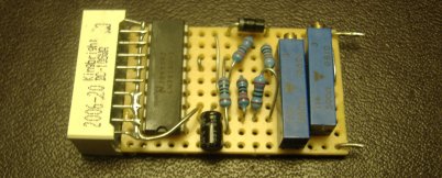
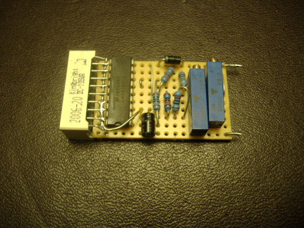
Solder the rest of the chip pins in if you have not done so already. The picture shown has everything soldered but it does show the way the LED module is mounted on the end of the board.

6. Add the resistors now. I recommend the order to be 100R,22K,10K,1K and 270R then the two variable resistors, 200R and 500R. Remember we are looking from underneath here.

Things to note:
There isn’t going to be very much room: Maybe keep the 100R resistor a couple of mm off the board to as to be able to fit the 22K resistor in because one end of the 22K plugs in directly under the 100R resistor. Keep the 22K resistor close to the board because there need s to be room for a diode later. The 1k resistor need to be at least partially standing up as it’ mounting holes are too close otherwise. same goes for the 270R resistor which need s to be completely standing up (in a “u” shape with the resistor on one side and a length of lead on the other). It’ll also need to be pushed over a bit to reduce it’s height. The 270R resistor does something a bit sneaky here because of space. One of it’s leads emerges into one of the track cut-outs you made earlier. See the diagram above.
The 200R and 500R variable resistors are straightforward to mount. Note that they are staggered with respect to one another. Please bend the leads inwards over the tracks just like with the chiip to prevent them sticking too far below the board.
7. solder in the diode with the cathode (the painted end) towards the chip. This diode will prevent current from passing to the chip’s power supply if the monitor’s terminals are reversed.

8. get the small capacitor and bend it’s negative lead (normally next to the stripe) directly outward at the case. Bend the positive lead so that it follows the first lead but a couple of millimeters lower down further away from the case. The two leads should be parallel now and pointing away from the case to one side (the side with the stripe) Now poke the leads through the board as show in the diagram. The capacitor shoulld be lying down directly over the diagonal wire link. Trim the leads and solder it in.

9. As shown on the picture below: You see the 10 anodes on the LED module which are not soldered yet? OK. Bend the first and last pins down by a few degrees, maybe 20. Now fashion a bit of wire so that it sits against all the pins, under the 8 straight ones and over the two bent end ones. Leave a couple of centimetres free at the end near the notch on the chip. This need s to go through the board next to the Vcc (+) pin on the chip which is pin 3 it is the same track as the positive lead on the capacitor. Make sure everything is straight, Solder the wire up to the board then all of the LED module anode pins. It’s a bit fiddly.
10. The boards are connected by leads or pins on the top and bottom track of the board on the other end to the LED end i.e. close to the variable resistors. The positive track is the one which is closest to the adjusting screws on the variable resistors. It also leads to the diode. The negative track is the other one.
The positive track and the adjustments mark the “top” of the board i.e. the bargraph display starts from the bottom of the board closest to the the negative supply at lower voltages and finishes at the top of the board closest to the positive supply.
One mounting idea for attaching lots of these boards together is to attach short leads, half a centimeter to the tracks pointing back away from the board (I put mine through the board first)
Then the boards can all be soldered next to each other to a master boards which is also 10 “holes’ high. This keeps the spacing correct and your LED modules can be glued to each other with superglue to make a rigid multi display. Each individual element is exactly 1 inch high, 0.4 inches wide and 1.95 inches deep.

Have fun!

James May in the UK

James! This is brilliant.
So glad you posted the DIY at last because I’ve been telling everyone who will listen how incredibly useful your LED monitor is; I’ve pointed more than a few people to part 1 for the details.
It’s been an invaluable tool for initially weeding out the weak & dying floodies from the pack, and for protecting the longevity of the replacements & remainders.
For anyone with an older, less-than-perfectly-balanced pack, driving an EV without a monitor like this is akin to playing Russian roulette with the batteries.
cheers!
Darin
Would it be possible to get a parts number list from some place like mouser.com? The circuit looks simple enough to build, but picking parts always seems hard.
I can’t believe I don’t see anything like this on eBay…
hint, hint!
I’ve done a surface mount board layout for this in Eagle. I havent built it yet, but I’ll donate it.
How’s this?
Now, if we could go together and make up the boards – i’ll take 25 right off the top.
Bob
LED BAR/DOT GRAPH BATTERY CELL MONITOR
PART SOURCE PART NUMBER
LM3914 bargraph display IC Mouser 526-NTE1508
10 DIL LED bargraph display Mouser 604-DC10GWA
10 uF electrolytic capacitor Mouser 140-L10V10-RC
100R resistor Mouser 660-MFS1/4D52R1000F
1K resisitor Mouser 660-MF1/4DC1001F
270R resistor Mouser 660-MF1/4DCT52R2700F
10K resistor Mouser 660-MF1/4CCT52R1002F
22K resistor Mouser 660-MF1/4DC2202F
200R precision cermet trimmer Mouser 652-3006P-1-201-LF
500R precision cermet trimmer Mouser 652-3006P-1-501-LF
IN4001 silicon rectifier diode Mouser 621-1N4001
stripboard 10 holes x 16 holes Mouser
(strips run along the 16 hole side)
If produced for a group, a simple three position switch to toggle 6V, 8V, 12V, could be added to meet the needs of everyone.
Hi Everyone
Thank you very much for all the feedback. If somebody tries to make one these meters and had difficulty or if the instructions are hard to follow then I’ll update them as required.
Darin: Thanks for the product endorsement! (I sold 8 of these meters to Darin last year)
Danno: Maybe I’ll make some more of these, I haven’t decided yet. In the mean time, I’m sure somebody else can improve on this design.
Jon: If you send your stuff to me or to Jerry, we’ll post it up if you want to share it with everybody.
Bob: Thanks a lot for going to the trouble of looking up all those product numbers. Remember to change the 22K resistor to a 56K resistor for a 12V meter.
Nick: I’m not sure, I think it would be cheaper and easier just to supply two or three different resistors if you were providing a kit or just put in the right one if you’re making them to order.
To make sure you order the correct voltage divider resister:
22k for 6volt
33k for 8 volt
56k for 12volt
Simply substitute the correct value, 22 or 33 or 56 in the part number.
Great info. Thanks for sharing. I did not see, but how long does it take to assemble one of these, and approximately how much are the components? Then I will know if I should give this a go or not.
Cost?
My initial pricing using the mouser catalog runs about $465.00 plus shipping for 25 boards.
Based on the retail prices listed for the parts specified (all resistors are 1%, there may be cheaper options) the total would be about $18.75 for each element.
BUT: the LM3914 lists for 9.14 each at Mouser then you add shipping.
I paid 3.54 each with shipping on ebay. If cost is an issue, look around and you can find some pretty good prices.
Bob
I can get the Led driver (070017-51 3$) bargraph (170159-1 2$) and trim pots (1$) locally at www.Addison-Electronics.com
The other components are pennies each so we’re looking at about 10$/ea.
They ship internationally.
It took me between twenty minutes and half an hour to assemble these when I got in a rhythm. Sometimes they didn’t work first time because of a short or a dry joint and took a little longer. It takes another 5 – 10 minuted to calibrate them using a variable voltage supply.
Just a thought – I haven’t checked your parts lists but make sure that the variable resistors are those long worm screw type so that they fit the design of the board and that the capacitor is a miniature one. Mine are around 4mm in diameter and 6mm high. That way you’ll be able to stack the boards with no interference.
James,
All good cautions.
Yes, I think careful shopping can produce these boards for 9-10 dollars cost of parts.
Regarding the parts listed from Mousers (they are available at dozens of places, I just happened to have a Mouser catalog handy):
the caps listed are stated to be 3×7mm – should be small enough.
the trim pots are high precision 10 turn “long” style as pictured above
the resisters are all 1% tolerance, and 1/4 watt in size
Are there any other things to watch for?
I’m looking at stripbpard that comes in 5 inches by about 6 inches – thinking I can get 4 or 6 pieces out of each – does this sound workable? (unless a nice mask for etching our own becomes available.)
Thanks,
Bob
I would think that a Eagle design could be sent here:
http://www.batchpcb.com/
and have the boards made up that way. Little less fuss, and the soldering becomes easier.
It would be even cooler if we could come up with an isolated version. That way all the high and low references of the LM3914s could be tied together. Then you could use one set of pots to control all the upper and lower limits of all the LEDs. Also it would be nice not to have the high pack voltage inside the passenger compartment. Any ideas?
For the initial design, I’ve come up with pricing at Newark.com.
~95CND$+shipping+taxes
Parts list for 12× 12V:
58K2341 12
97M6266 12
58K3919 12
58K3945 12
01F8182 12
01F8183 12
33K4103 12
18C8911 12
58K3886 12
58K3885 12
38K4677 12
Paste that into their “Quick Paste” window in the shopping cart area. Adjust the 58K3945 part for 6V or 8V as needed. Use the voucher “SAVE5C” to knock 5% off the total, and voila!
So that’s less than 10$ a piece delivered next day UPS.
My order has been placed, I just have to pick up the stripboards, some soldering supplies and a used bench power supply — any excuse for some new tools!
-Nick
Couldn’t you have gotten your strip board from them too?
Part#: 05M1088 $10.95
38 strips X 84 holes
You should be able to get 15 boards from that, or 10 to 12 boards and the back board maybe.
http://www.farnell.com/datasheets/79883.pdf
You can get the
LM3914 bargraph display IC
from Jameco Electronics
Part# 24230 @ $2.39 ea.
Min. order is 1.
From what I have seen, Mouser would be a good place to buy the other parts.
here is a cool idea too.
http://autospeed.com/cms/A_110623/article.html
I can’t help but liking ideas that are on the cheep so read all the way down.
Update: I ordered parts from three sources. Two of them delivered today. I have in hand everything for my 25 boards except the LM3914’s. I’m sure they will be here before I get all 25 boards cut to size and the strips routed out. The good news: I’m on my way and haven’t yet made a single mistake.
Warning! I have just seen a slight mistake on my diagrams. The chip is wider than shown on the diagrams. It’s pins are four ‘holes’ apart rather than three. This means that the left hand row of pins are one hole further left than shown, that is, one hole closer to the LED array. I’ll see if I can fix the diagrams in the next few days.
James,
I saw that – the photo of the finished board at the top of this page reflects the difference – just be sure to place the LM3914 one row towards the front and not towards the back.
We could always make the boards a whole .1” longer, but I don’t see a problem – just be sure to put the chip in the correct verticle columns of holes.
Yes, there’s no need to make the boards longer. You can fit everything in this way, it’s just a diagram mistake.
I think it is a good idea to fit fuses close to the batteries on all the wires leading to the meters.
Isolation: It would be better to have meters in the car electrically isolated from the batteries to reduce shock hazard. I don’t it can practically be done with this circuit unless anyone else has ideas.
The Paktrakr is isolated, which is an advantage. It is not quite as resposive or easy to read as these meters in my opinion. Maybe someone could design a PIC based circuit to drive LED bargraph array based on the output of a Paktrakr remote. They output serial ascii values in a CSV stream I believe. Doing this would reduce high voltage wiring.
LM3914 is $1.75 at AllElectronics.com http://www.allelectronics.com/index.php?page=search&search_query=lm3914
The LEDs are $1.50 in quantity greater than 10
http://www.allelectronics.com/index.php?type=&page=search&action=&id=&skip_redirect_suffix=&view_id=7affabb69887942aaf4581ebe3f6f19841e6af10&search_query=bargraph
I used these boards which are $0.75 http://www.allelectronics.com/make-a-store/item/PC-1/SOLDERABLE-PERF-BOARD/-/1.html
Another important idea is fusing and wire size. Each LED bargraph monitor draws very little current so the wire doesn’t have to be a heavy gauge. What you do have to consider is the insulation of the wire. True each wire is handling about 12 volts but you still have to consider that the entire pack voltage may be on two adjacent wires in your cable.
Fusing is another consideration and you should keep in mind the entire pack voltage when choosing an appropriate fuse voltage.
I’m not sure if this has been mentined but… Another consideration is the calibration of all the monitors and I propose that when calibrating the upper and lower voltage values you utilize the fact that the LM3914 has a very small window of overlap that causes 2 adjacent LEDs to be on at the same time so as to avoid ever having no LED lit up. You can calibrate more accurately using this concept. ie with all the + sides connected together and all the – sides connected together, you apply a voltage that is in the middle of the value for the lowest and next lowest LED and adjust the calibration pots so both LEDs are on. Then you do the similar step for the 2 higher voltage LEDs. electricDeLorean.com
Hi Dave,
This is a very helpful contribution. Thank you.
In fact I was calibrating them at the exact point the bottom LED went out and at the exact point the top LED was lit alone and not overlapping with the second LED
Another note. The boards I used have mounting holes in the corners and I bought a length of 6-32 threaded Nylon rod and cut it into 4 pieces. These pass through the holes for mounting. in between each board is a Nylon spacer, ?3/8” if I recall. I finally have it all working in the eLectric DeLorean. I have a photo of the finished product but not of the insides and boards yet.
Well done Dave. I feel honoured to have contributed in a small way to an eLectric DeLorean!
Hi Dave, thanks for the useful information. I have one question, how much would one of this LED Bargraph battery monitor cost? Can I get it off the selves?
They shouldn’t cost more than $10 each for the parts. I do not know of anyone selling these but the unit at http://autospeed.com/cms/A_110623/article.html as DanP above noted can be purchased.
I’ve just completed 3 of the 12 I need.
I have redone the component routing for a board without traces. Thanks to Dave for pics of his implementation, but given we didn’t quite have the same components, I had to move things around a bit. Here is the diagram.
http://docs.google.com/Doc?id=dhmzznh8_6g795t582
Very nicely done, Nick!
Nice! This meter is small, slick and convenient. But, if you have room behind your dashboard, you could mount a $3 digital multimeter (Chinese item sold at Harbor Freight in the U.S.) with lcd display.
However, it runs on a 9 volt battery, so you would have to keep changing that, or hook it up to your vehicle’s system with a resistor inline to drop the voltage. When the meter goes dead, you know you have less than 9 volts.
Maybe the programmable Sears Wood Carver could cut the copper strips then cut the individual panels from the main panel.
Fusing should be done both at the board and at the battery (cell).
On the board you can use a SINGLE strand of wire from a multi-stranded conducter (10ga for example).
At the battery, rather to the battery, not much works better or is cleaner than telephone wire. It’s so small that any short will melt the conductor long before the insulation.
PS: THANKS GUYS! This stuff is GREAT!
You can replace the Vishay trim pots with some much less expensive pots and shave another $2 from this.
The 01F8182 is $1.43 but the 05N1557 is just 0.44.
Similarly the 01F8183 is also $1.43 and the 05N1562 is 0.44. They’re the same specs.
Great little design. I watched the YouTube and this is JUST what I was looking for, a real time image. I don’t want to program a computer while I’m driving. But to get a real time visual indication of each battery while operating is the tits.
With the above substitutions, you should be under $8 in parts per battery.
Many thanks.
Reading about how this was used in the Forkenswift, it occurred to me that it would be handy if the meter could ‘remember’ the lowest voltage for each battery. Maybe an amber LED could be latched ‘on’ for any battery that dropped below the danger level while the go-pedal was pushed? It seems to me that this would help locate bad batteries without having to focus so much attention on the gauge.
I’ve been looking for a monitor like this.
I just hope I can get it together without damaging anything.
I’m confused about where the pos/neg from the battery attaches.
Hi Fellas, sorry I haven’t been around for a while!
Grouch: I don’t think it would be easy to modify this circuit to latch an LED on at the lowest voltage. I think it might be better to start with a digital device like the PakTrakr. Indeed, I am thinking of making an LED bargraph output to this device for my next project. That’ll remove the disadvantage of having to bring high voltage wires all the way to the display.
Calvin. Hi The pos / neg from the battery attach to the top and bottom track at the back of the board. you can see two short bare wires in the colour photo at the top of this page. The track which leads to the diode is the positive. The meter reads the voltage which supplies it so you only need two wires to each meter.
Thanks James, All parts are in execpt
LM3914 bargraph display and IC.
I’ve got to find the stripboard, All I’ve found so far is perfboard and it looks different than the strip.
Believe it or not, This is going in my lifesize R2D2 to monitor his batts.
It will be a GREAT addition and the other builders will like it also.
Thanks again for helping me and if I can get it soldered up I’ll really enjoy your idea.
Calvin
So what is the calibration procedure for the two trim pots? What do each do?
Jack Rickard
Very informative post on baragraph battery.
Hi Jack
Sorry it’s taken me so long to reply. The 500R trim pot trims in the bottom voltage of the range, the voltage which lights the bottom LED. The 200R trim pot adjusts the top voltage, the voltage for which the top LED (or all of them in bar mode) comes on. Since one trim pot affects the other to a small degree, you will probably need two trimming iterations to adjust them in. You’ll need a variable voltage supply and a digital voltmeter. You just need to calibrate to the top and bottom voltages you want to read. the bargraph is proportional between those.
I have just seen your entry on EValbum, it’s a pretty car!
Oops, my instructions are wrong! Sorry, the 500R trim pot adjusts the top voltage, not the bottom, it should be adjusted first. Then adjust the other trim pot to adjust the bottom light. The voltages I suggested were for flooded batteries. AGM batteries have a higher voltage at full charge. Refer to your battery literature.
I just finished breaking up the tracks as shown at the top of page 2 – for 6 boards plus 2 spares. I used my Dremel tool and a very small rounded grinder to do this.
The next step, soldering in the links, has me a bit confused. The instructions say to use uninsulated, pretinned single strand wire.
What I don’t understand is whether the links should be soldered to each track over which they cross. At first I thought they should because the links are uninsulated. One link, the one that runs vertically and is located 7 holes from the left, spans 6 tracks, then continues diagonally to the next track above and one hole to the right. It seems to me that soldering this particular link to every track it crosses doesn’t make any sense because it defeats the usefulness of the short link just to the left of it.
So should the links be soldered to all tracks they cross?
One more thing: I’m no expert at building electronic devices. What is the best way to do the soldering? Should I pre-tin the wires or try to add solder to the links as I insert them in the holes? My soldering iron, although good for normal-sized jobs, seems to be too large for miniature projects like this one. What kind of soldering iron would be best?
Thank you.
What a nice post with great information about bargraph battery….ridiculous!!!
To “motorhomes for sale”, what is your problem? I thought the purpose of this forum was to help each other.
By the way, “motorhomes for sale” is a glitched up non-functional website which may be a source for a virus. Don’t go there.
Hi
As I understand ths unit one requires a monitor for each battery used in the cars pack is this correct?
My second question is where can I find a anolog meter that will measure the pack voltage more accuatly than the bar guage fitted on the dash? FSD to be 100/120V DC.
Thanks for the circuit most helpful
M3NWH
Identifying the pin numbers for the LM3914 chip and the 10 LED display were not obvious (at least not for me).
I did some reading and found that the chip has a half circle on one end as you look down on it from above. To the left of the half circle is pin 1, with pin 18 to the right.
The bargraph display has a corner cut off as you look down on it from above. Pin 1 is at that corner, with pin 20 to the right. Also all pins on the side with the corner cut off are anodes, with cathodes on the other side.
I wish this comment function offered a way to include diagrams, so that I could show you exactly what I mean.
You might take a look at the Yahoo Zenn forum. I have included diagrams there.
I enlarged the photo at the bottom of page 2. There should be 6 links soldered to the copper side of the board, but none seem to be there. Were they soldered in later?
Thanks.
Thanks for posting the details for this great idea, James! I can get the parts locally, so I’ll make a 10 stack for my Mini Pickup conversion.
I’d like your comment on a couple ideas:
1. Instead of fuses at each battery, would it be possible to use resistors? If a short occours the voltage would just drop. As long as the display is in dot mode the current draw should be the same over the voltage range, so the resistor should not add an error.
2. Are the pots necessary? IMO pots are unreliable. With 1% resistors I think the accuracy should be good enough. What I’m interested in is comparing different batteries, not the exact voltage.
3. Is 2 leads for each board necessary? Could I connect positive on the bottom board to negative on the next one? The two leads in question are connected at the batteries anyway. Then 11 leads for a 10 stack would be enough.
Electric greetings
Tom R Simenstad
Oslo, Norway
PS. It’s morning here now.
Well, I gave it a try – but no joy. I spent 2 days attempting to assemble just one meter. It quickly became obvious that this is way beyond the capabilities of the average DIYer. For one thing, professional skill as a solderer is required, for another, your vision must be up to par (and magnified viewing equipment is required because this project is an exercise in miniaturization). I can’t believe that even a pro could put together one meter in just a few minutes. Days is more likely.
I managed to assemble one meter, doing my best to follow the instructions and avoiding shorted out tracks, but the result was zero. I connected the meter to one fully charged lead/acid battery and got nothing – even after tweaking the two potentiometers.
The instructions were meant for pros, not the average EV enthusiast. Things that were unclear included information about device pin numbers, track links, and how to test circuit integrity as the project progressed. These things may be obvious to some, but certainly not to most.
Has anyone other than James May actually built one of these devices? All of the comments I have read here say almost nothing in that regard.
After this experience, I recommend the PakTrakr for most EV owners.
By the way, I have 6 sets of unused parts (except for the boards) available for these meters for free. Just pay the postage from 43085, and they are yours.
Jim
You’ve got a deal, Jim! I can’t find your address, klick on my underlined name at the top of my post and email me at the adress that appears at EValbum for details. I’ve got PayPal.
A minimum of knowledge and experience in electronics is certainly needed for a project like this. IMO James has given all necessary information.
Tom
To Tom S.
Sorry, Tom. Parts are no longer available.
Jim
I note that 1% resistors are needed for this meter where as 10% or 5% are much more redly available. Why is such a hight specification needed?
I built one in about 45 minutes using perf board, not strip board. It was predictably enough a wiring mess, but convinced me it would work.
I then did a circuit design in PCB and gschem in Linux and uploaded it to Sunstone circuits Ordered 4 boards and got them 4 days later at $60 each. The result was a very nice little board about an inch tall and an inch and a bit deep. That certainly makes it easier to install.
All that said, I decided I wanted both a wider range, and still very small granularity. I run Thundersky TSLP -90A Lithium Ion batteries. These typically stabilize after full charge at about 3.45 volts per, for 13.8v at rest. The discharge curve is quite flat to 3.0 volts and fairly steep afterwards. 2.5 volts is the minimum voltage “at rest.” Of course, they sag a bit under current load.
So basically, I’ve opted to use 2 LM3914s and a 20 segment display. I want to show 10.8 v to 13.8v and still have .15v granularity from one bar segment to the next.
I also found some Vishay CT94EP series pots that have a much smaller footprint, lay closer to the board, and can still be placed so I can adjust from the top.
I should be able to put together an array of 16 of these wide for my 16 batteries that is 2 inches high and a little over 7 inches wide.
I hadn’t wanted to put pack voltage in the passenger compartment. But I think I’ve figured a way where it won’t hurt anybody.
I’m adding a right angle MOLEX 8 pin connector to the back of the card.
I’m then going to design a backplane with 16 of the associated receptacle. In this way I can just plug in cards.
The backplane will feature two RJ-45 jacks.
I’ll wire the batteries to terminal strips in the forward and engine compartments. Then I’m going to run ethernet cable (8 pins perfect) from the terminal strip to ethernet plugs in the passenger compartment. The plugs will simply plug into the jacks on the back side of the backplane.
No fuses. The wire in ethernet cable is sufficiently small that it can’t carry much current at all. If there’s a mishap, I’m pretty sure they’ll let the smoke out before hurting either batteries or people.
The only downside is such small wires might add a little resistance. I’ll have to recalibrate on the car. Which is kind of the reason for the terminal strips. I can use a bench supply and multimeter in the front compartment at the terminal strips, and then just tweek the associated bargraph for the upper and lower limits.
It will be tedious, but it should be very accurate.
The PCB is the most expensive part. But I’m not dealing with strip board or perf board 16 times at any price.
It took about 45 minutes or an hour for me to do one the hard way.
With a PCB, I think I can throw one together in about 10 minutes. It will take longer to calibrate than to build.
Jack Rickard
I think Nick Drouin’s component layout – link in post #33 – looks nice and tidy, so I adopted it although it is 1 strip wider than James’ layout.
I can’t find 1% resistors at my supplier, they are either 5% or .1%. I’ll assemble one test sample using the 5% resistors from the set that I’ve got from previously to see how it works out.
I’m taking a survey.
Have you built the bargraph project yourself?
Is it installed and working?
In post #58 Frank Gear asks if 1% resistors are needed. IMO no. There are pots in series with the resistors (except R1 and R2, which are not critical) that takes up any incorrect resistor value.
Jim Calvert:
I’ve bought the parts for 10 meters, have cut the strip board to size and I’m presently researching and calculating to adapt the bargraph voltmeter for 12V lead/acid AGM and to read from 10.5V to 14.4V. I’ll also test the teories that I asked about in post #54. I’m not the fastest as I have several projects going at the same time, but I’ll post the results as I progress.
Tip: the side of the strip board with the copper strips is called the solder side. All components and straps are mounted on the opposite side, the component side. The drawings are viewed from the copper side, as this is the way you see it while you solder. It takes a bit of practice to work under a magnifying glass, but at my age it is needed. Strong lights also helps.
The diode, IC, LED bar graph and capacitor needs to be positioned the correct way: The white ring around the diode should be positioned towards the IC. Everything is still OK if the diode has been positioned the opposite way. The IC has a notch on one short end, this must point in the right direction, see print drawing. If positioned incorrectly, the IC is probably broken. The LED bar graph has one corner cut (it’s barely visible). The side with the cut corner points away from the IC. Everything is still OK if mounted the opposite way. If the capacitor is turned around it will blow up.
Be carefull not to use too much heat when removing components to turn them around. Solder wick can be used to such up the solder. If they don’t come loose in 5 seconds, let them cool and try again.
The parts that James names “links” are what I call “straps”.
I’ve got light! But the end voltages are way off what I want. It seems that I lost the expanded scale in my modification.
I didn’t have a variable power supply at hand so I used a 10kohm pot. Each end terminal of the pot connects to each battery terminal. Negative to the LED bar graph connects to the negative battery terminal. Positive to the LED bar graph connects to the center wiper terminal on the pot. Now the voltage to the LED bar graph can be reduced.
Hi,
This is Naina. I am not very sure if this is the right forum to ask this…
I have recently shifted to New York and am looking for an electric bike. My friends have recomended R Martin Electric Bikes(http://www.rmartinbikes.com/ ) as they are using it. I am not very sure that whether I should buy from there or not? Can any one of you help with any suggestions?
Thanks much
Naina
Hi Tom:
Thank you for the great tips. Very much appreciated.
Jim,
To answer your post #61:
I’ve built three.
They work on the bench, my car is not yet complete.
The first took serveral hours as I was doing the component layout and solder order. I will update my diagram to include the soldering order, which helps quite a bit.
The other two I did at the same time and took about two hours to complete.
A solid 15 mins per board is spent bending the pins on the LED module to simplify soldering.
I built the three while on a business trip, at the hotel, in the evening — no work lights, magnifying glass or bench clamps — a bit of a challenge to say the least.
I’m hoping to get the build time down to 30 min at home on the workbench.
I had a chance to present them to the NJ EEA chapter meeting in November.
Thanks, Nick.
Looking forward to your future posts.
Jim
Ok,
I’ve added the soldering order and a few notes. Here is the link again:
http://docs.google.com/Doc?id=dhmzznh8_6g795t582
I’ve now assembled and tested 3 LED bar graph battery monitors and I think I can answer my second question in post #54: “Are the pots necessary?”
No, they are not. I used 5% tolerance resistors and all three monitors are within 5% of each other. I did check the actual resistance in each component and matched them for minimum difference. With a little mixing of R1 and R2 between each monitor I’m sure I can reduce the tolerance further.
After a little tweaking of the fixed resistors (I’ve got a set of 10 of each in the E12 series) I’ve got an accuracy of 1 % between the first three monitors over the whole range. I’ve assembled them selecting the resistors that I expected to give the highest and lowest reading, but it didn’t turn out that way. By the way, 1% is also the tolerance of the two digital voltmeters I used for the test. The test was performed at an ambient temperature of 19 degrees C. I’m not going to bother testing at different temperatures, but expect the IC manufacturer’s data to be correct. The given operating temperature range is 0 to 70 degrees C. Fine for California, but I wonder how the monitors will cope with the Norwegian winter temperature, down to -15 in my area.
I punched out another two. Unfortunately, the build time is still 1hr/each.
Indeed, perhaps a simplification of the circuit is in order; but that will be for next time… meanwhile, I have components in hand and will build the remaining 7 the same.
Pics from the build:
http://picasaweb.google.ca/nicolas.drouin/EVLEDBargraph
-Nick
http://img23.imageshack.us/img23/8968/skjema12vbattovervtrsrb2.png
This is what the cirquit diagram looks like with a not-so-expanded scale. I want to monitor both discharge and charge voltages in case I go for one charger. LED #1 comes on at 10.3V and #10 comes om at 14.7V.
Having assembled 3, I felt confident that I could not add further improvements and the accuracy was sufficient at 1%. A marathon electronic weekend was spent assembling the remaining 7 LED bar graphs. Effective working time for the 7 units was 5 1/2 hours installing all ICs first, then R4 and so on along the board. I had previousely cut the strip board to size and cut the strips between the pins of the IC by hand. Omitting the pots and using Nick’s lay out as a base I got 11 by 11 hole strip boards.
Some photos of bad quality (I don’t have a digital camera, but use my old cell phone ;-)):
Singe board component side: http://img218.imageshack.us/img218/1044/pcbcompue8.jpg
The capacitor is attached with a blob of contact cement for durability.
Single board solder side: http://img218.imageshack.us/img218/8845/pcbsolderjm9.jpg
Stack top/front view: http://img207.imageshack.us/img207/5711/stackfttopas6.jpg
The numbers helped me fine tune each unit by moving resistors between them as I selected each resistor for max accuracy.
Stack top/rear view: http://img12.imageshack.us/img12/1706/stackrrtopbc6.jpg
The vertical strip board is the width I had left. All 10 units connected in parallell at this time for test purposes.
Sorry I didn’t take the time to make an album like Nick did, you’ll have to open each photo individually.
Has someone administering this forum done something to fix it? Yesterday I could only see the first 73 comments. Now all of them appear.
I’ve never had a problem, Jim. I use Firefox internet browser. Different issues appear in different browsers even when the proper code is used in making the home page.
Tonight I’m going to disassemble the LED bar graph into 10 units, clean the flux off of the solder side and apply a few coats of protective coating on both sides. The coating is good for the varying temperature experienced here in Norway. When the interior is quickly heated after sitting in the cold all night dew/condensation forms on everything. The protective coating is an electrical insulation to prevent creep current and keep the accuracy in humid conditions. I wouldn’t bother doing this if I lived in California or another place in the tempered zone.
I think it would be a good idea if someone who has assembled the LED bar graph battery monitor to James’ specifications would note the voltage on each pin of the IC and the exact input voltage as it will be a good source when finding faults. Note that the voltage on one of the pins 1 and 10 through 18 drops only .6 (zero point 6) volts when the corresponding LED segment lights up.
Just to throw out a somewhat related ?: How hard would it be to do this same concept in an LCD bitmapped display (somewhat like a Prius display)? That way, you would have finer granularity, and your display space could also have other pages of info.
Where can one get displays of a certain size (like to fill the old radio hole)? Is it even possible?
I got here after reading EAA’s CurrentEVents, Feb. 2009 issue, p. 42.
Chuck, it can be done and EV friend of mine has done it. http://www.sixbynine.no/?page=ranger
Displays will be avaliable from your nearest electronics supplier.
Ok,
My photo album is up to date at: http://picasaweb.google.ca/nicolas.drouin/EVLEDBargraph?feat=directlinkThe last 7 took me 5 hours, so a bit of an improvement. But lets just say I wouldn’t want to be paying someone else to put these together… the labour would be five times the price of the components!
I got it all fitted into a project box. I ended up using a screw-down connector to act as both a spacer and strain-relief.
Again, the wiring is at:
http://docs.google.com/Doc?id=dhmzznh8_6g795t582&hl=en
Thanks for useful tips.
I posted a video showing my monitor in action. It’s a bit jumpy but I think it is helpful. Thank you for this informative project.
http://www.youtube.com/watch?v=GTguQh_p5I8&feature=channel_page
Great job, James!
I wonder if anyone has considered using a multiplexer and digital display to sequentially select and display data from the different batteries. Then you would need only one display (it looks like you have about 17 in your stack now). The unit could also give an alarm and identify the battery number in case of an unvervoltage or overvoltage. (I know…Easier said than done, right?)
Mark,
The goal is to see all the batteries at the same time. This will identify the bad ones, and you get a very good feel for the dynamics of the pack, its sag and recovery.
The Paktrakr is an off-the-shelf component which does what you describe; but does not offer a side-by-side view of the whole pack (unless you get some add-on 3rd party displays). Its also quite a bit more expensive (if you don’t count your time while assembling these LED devices).
Nice video, Dave. I got a kick out of seeing the “western prairies” topography on your bargraph as you drive. The pattern my mismatched oddball pack makes is more like the Rocky Mountains. :)
And I agree with Nick: the value in this display is the ability to “see” the performance of each battery (or module) in the pack relative to the others in real time.
It very quickly became my #1 monitored gauge.
While driving and ‘full’ I use the battery amps gauge to stay below 1.5C (150Amps in my case).
Once I’ve used up half of my pack (roughly), I use the sag of the LED monitors gauge stiffness (how fast the batteries drop in voltage under load) and springiness (how fast they return to no-load voltage) to gauge how much I have left in my pack. This is more of a ‘feeling’ than anything objective. But I have never found myself stranded, nor lacking the power to stay on the highway.
Moreover, I have two chargers which require two 110VAC 15A plugs. At work I only have one 15A plug. So I go out at lunch and swap plugs (front pack of 6 batteries, to back pack of 6). I rarely leave work with all batteries at the same charge level. Having this LED monitor helps me ensure I don’t abuse the 6 lowest batteries.
Well done Nick!
These meters are really handy aren’t they!
I am not running any at the moment, I am considering making an PIC based LED bargraph display linked to the output of a paktrakr but that’s on the back burner.
For now, for those of us who charge all out batteries in series, I’m working on a low cost sequential charging system to blow away those unequal blues. If it works, I’ll put up a post about it.
Incidentally, redundancy has forced a change of career and I’m reskilling from IT to self-employed electrician. Good luck to me!
Hi guys, I’m just in the process of sourcing all the bits to build a total of 18 of these eek! 8v for my conversion project. Did we establish they are good to use without the variable resistors, if all components are within 1%? (saves quite a bit on cost of 18!) or will I still need them to tune the upper and lower voltage ranges?? Well done on these James, I really like the concept, going to have 2 rows of 9 in the centre console :) PS, good luck with the Electrician training, it’s what I used to do!
Hi Paul, thanks for the kind words.
Remember that the downside of these meters is that you have to drag high voltage wires through to the dashboard which isn’t ideal. Don’t forget to provide fuses at the battery end. If other people have had good luck with the fixed resistors then I’m sure they’ll be fine. You could always trim on resistor value when you make them if there are any differences between the meters.
One possible advantage of the trimmers is that, in practice, you might want to adjust the working range of your meters after trying them out to suit your range / style of driving. Adjusting trimmers might be easier than changing out resistors.
I don’t know where Wootton is but If you are ever near Coventry I’d love to meet up, not to many EVers in the UK!
Well, I finally finished 18 of these babies! Wow, that was tedious, and I can’t see straight anymore!! Took just over 15 hours in total, but very pleased with the results. Only thing I did do was buy two colour leds to start with, with three red segments, thought it would be a nice touch to show a low state of charge/pulling too much current warning, but guess what? the red segments turned out to be at the top!! Doh!! who’d have thought. Anyway it looked ridiculous, so I replaced them with green only leds. I did also use an array of minature relays at the rear of the boards, (if you use double pole relays you only need 9 to isolate all 18 boards) these are paralleled up to an ignition switched main on/off switch. Having pack voltage behind the dash doesn’t worry me much, as long as the wiring is correctly and safely instigated with low rated fusing (500ma) at the battery end on all the leads it’s fine, after all here in the UK, all our appliances are 230v, and that doesn’t seem to worry anyone!! lol
Hi James!
I want to use one of these to monitor my 12v acc. battery. The only problem is, when running the test circuit (I plan on using the existing generator/altinator instead of a DC/DC converter) the monitor maxs out and can’t be adjusted. What resistor do I need to replace with a different value to use a range of 10 to 15 vdc? The battery would show 12 volts until it is charged, then it is about 13.5 to 14.5 volts when charging. Also, what value would work for this.
As a side thought, I was thinking about making circuit boards that could just have parts installed and soldered (sort of like a kit either with or without the parts). If there was enough interest, I could price a quantity of boards and let you know the price for anyone interested is a simpler way to make these. The more that are ordered at one time, the cheaper they would be.
If there is enough interest in this, post here and I’ll let you know about what a circuit board would cost after getting a quote.
Thanks for a great project!
Jim B.
I’d like to build a 20 dot meter like Jack’s in response #59 for 12V batteries. Is anyone willing to share the schematic/board layout for that design here?
Thanks,
Eric.