
LED Bargraph battery monitor - part 1 · 18 May 07
Hello everybody,
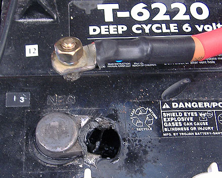
About 6 months ago I wrote an article here . The idea was that I would be able to avoid my nemesis, unequalised batteries , and have early warning of bad connections like the one which caused this terminal failure in my car. Argh!
The battery monitor was fairly successful but only gave a crude qualitative measurement of voltage drop. I have been looking for something better. Something with which I can see the actual voltage each battery is at.
When I saw the battery monitor on Jim Fell’s Seicento I had to have one. It’s based on the robust LM3914 LED driver IC.
The circuit I found and adapted can be found here. National Semiconductors have kindly provided an example circuit and some very good explanation.
I adapted this circuit to show 10 lights for 6.37V and above and no lights for 5.75V and below, with the rest of lights showing about 0.6V intervals. Each interval loosely approximates to 10% DoD (Depth of Discharge). Here’s the schematic: 
Here’s a table which shows number of lights shown against voltage and State of charge (100- DoD):
1. 5.75V ~10%
2. 5.82V ~20%
3. 5.89V ~30%
4. 5.96V ~40%
5. 6.03V ~50%
6. 6.09V ~60%
7. 6.16V ~70%
8. 6.23V ~80%
9. 6.30V ~90%
10. 6.37V 100% upwards
The LM3914 has 2 modes: “bar” where it will show all of the lights up to a certain light and “dot” where it will only show one (or occasionally 2 lights at a time). I started off using bar mode but I found this too bright and distracting – it lit up the whole car. Lighting up all those LEDs also drew a higher current and generally read lower due to the associated voltage drop.
You’ll see that I have designed this circuit for 6V Flooded lead acid batteries. For those of you running 8 or 12V you want to replace Rx with 33K or 56K respectively. I tested this at 12V with 56K and it works just fine.

For each meter you’ll need these components:
LM3914
10 DIL bargraph display
10 uF electrolytic capacitor
100R resistor
1k resisitor
270R resistor
10K resistor
22K resistor (for the 6V version)
200R precision cermet trimmer
500R precision cermet trimmer
IN4001 silicon rectifier diode or similar.
a piece of stripboard 10 holes x 16 holes (strips run along the 16 hole side)
All resistors should ideally be 1% or 2% tolerance.
The electrolytic capacitor needs to be very small and short if you want to mount all the boards together as shown below.
Tools required:
Small soldering iron and solder
Adjustable power supply (5.5 – 6.5V for 6v batteries)
Digital multimeter
If you have made the circuits tidily you should be able to glue the LED modules together and mount the whole thing on another stripboard.

Now to put it in the car.
I have left out all of the relays I used in the original battery monitor and the unit is now permanently on. I measured current usage and found that if you are using “bar” mode with all the LEDs on, you can expect to draw about 100mA per meter at 6V, probably about half that at 12V. If you use “dot” mode then you’ll draw about 10mA per meter. Certainly for my battery pack this is a very small loss.
I am so much more confident in my battery pack now that I can see what each individual battery is doing. I am sure that it’ll make the batteries last longer because I’ll be able to know about a discharged battery before I cause a cell reversal or over gassing.
That’s all for now! Step by step stripboard instructions coming up in Part 2.

James May in the UK

James – nice work! I can imagine how useful it must be to see how the entire pack is doing at a glance.
This is something that will be of concern to us with the ForkenSwift because we’re using old batteries (which are bound to be more mis-matched than a good, new set).
I’ve already wrecked 2 batteries by discharging them too far :) – reversed cells. Nothing like learning by breaking stuff! Fortunately, free stuff.
I was a little bit late with this post. Did you see the link on this site last week to the PakTrakr device. I think it might just do what this does, and more. My meters would be good value if you don’t have too many batteries, or you could use one for the 12V lights and ignition battery as I do.
Great job, James! Thanks for the excellent article and circuit plans.
I don’t see any isolation or other safety feature, so I presume you plan on bringing full pack voltage to the dash?
Hi Peter, Yes, it does bring full pack voltage to the dash. It’s only 96V for me so not too dangerous as a shock hazard, still, it’s not ideal. Each wire is fused right next to the battery at 250mA so I’m not really worried about any short circuits.
A QUESTION FVERYTHING I HAVE SEEN SAYS 6V BATERIES LAST LONGER AND PERFORM BETTER. DO YOU AGREE
Hi Jack,
I haven’t used any other batteries so I can’t make a comparison. I think the 6V golf cart batteries should last well because of their thick plates and relatively large cells. And like you, I have also heard that they are particularly robust. The Trojans have a good reputation.Hi James –
I can’t find the Part 2 of this project. I must be missing something simple. Could you please post the link?
How has the monitor been working for you?
I have been monitoring a single battery with a DMM, like Dr Larry.
I monitor the one (of 8) which consistently shows the lowest voltage after charging/resting, on the assumption that it will be the weakest under load as well – though I’m not so sure there’s a direct correlation.
Having driven the ForkenSwift for a few charges, I can appreciate how nice it must be to know at a glance what’s going on with the pack.
Argh!
You caught me out! I haven’t written part 2. I actually thought when the PakTrakr came out that that device made mine rather obsolete.
Yes, it does work, it shows me my weak battery and what it is doing. I think my weakest battery is also not so good under load. It sags the most. Two reasons for this might be:
1. It’s SOC is lower therefore the acid is weaker and hte internal resistance of the battery is therefore higher.
2. The internal resistance of this battery is higher for some other reason.
It usually doesn’t use up water like the other ones.
Something weird about my meter which I have never figured out is that it reads low on the end batteries even though they are fine. It isn’t the wires, I have replaced some of them with bigger wires instead of hte original CAT5.
I think I permanently aged my weakest battery by letting one of it’s cells reverse under load before I made my power meter. Yes, they are worth having and show you when you need to do an equalisation charge or charge an individual battery.
I am considering upgrading to a PakTrakr.
You are running 6V batteries?
If I upgrade you might get a present in the post.
“I actually thought when the PakTrakr came out that that device made mine rather obsolete.”
But does the PakTrakr show you the collective pack at a glance, under load, like yours does? I looked through its specs and didn’t see that. It seems to me you can only cycle through the pack looking @ individual batteries.
An EV owner from Ottawa has lent me a simple box with an 8 position switch and a single analog volt gauge (well suited to our car’s 8 6v batt pack), but I haven’t installed it yet, because it also won’t show the whole picture at once.
Maybe I’m unneccesarily fixating on the at-a-glance battery comparison, but that strikes me as the most potentially useful feature of a monitor.
Is this suitable for my 6v 4A SLA? Is the state of charge the same for SLAs?
Thank you, James.
Hi Lucky,
Yes, I believe it’s the same for SLAs. If the full / empty voltages are slightly different (read your documentation) then you just calibrate the bargraph accordingly.
Hi James…
Any news to report on the DIY monitor vs. PakTrakr comparison?
Another option I’ve been mulling over is an Arduino-based battery monitor. I’m not really a hardware guy, and barely a programmer, but from what I’ve read of this open source platform, it shouldn’t be horribly difficult to build a 6-battery monitor (the board has 6 analog inputs) that can send live data to a laptop: arduino.cc
I may just look into this as a winter project. The pre-assembled board is about $30 US.
Sounds like a good idea. I will look in to it as well. My PakTrakr hasn’t arrived yet. :( I’ll chase it up if it doesn’t come soon.
Has anyone seen the new “EVision” unit that Metric Mind have on offer? It looks pretty sweet and includes an odometer, tachometer and even fuel gage driver. Bit on the expensive side though! It looks like an all-in-one solution if you were going to build an EV from scratch. www.metricmind.com/evision.htm
Hi Nick.
Yes it’s beautiful. It’s out of my price range too. It looks like a better featured e-meter. I must admit, My e-meter is a marvellous thing, it seems to give a good idea of my SOC (State of Charge) which is just about the most important think in an EV. My favourite two features listed for the EVision are instantaneous kW and Wh/mile. These things will help with your ‘fuel ‘ consumption.
My 8×6V PakTrakr and 8×6V remote have just arrived at the postal depot. I will try to fit in time to collect it tomorrow. I’m a bit excited to have a new bit of EV kit because it’s been a while.
This winter, James sent me an 8-battery portion of his LED bargraph after he got his PakTrakr.
Yesterday Ivan and I installed it into the ForkenSwift.
It’s awesomeness can’t be understated! Up to now, we’ve only been monitoring a single battery in the pack – the one we thought was the weakest. Rule of thumb: avoid drawing the weakest 6v battery below 5.25v under load to avoid damaging it.
Well, oops! Within 15 feet of driving, the dancing equalizer-like LEDs showed us several things, not the least of which was that we had NOT been monitoring the weakest battery all this time. We had a true dud in the pack that fell on its face under the lightest load.
It’s very cool to watch, and immensely useful. Every EV should have one (esp. if you’ve got an older, less balanced pack).
Thanks, James!
No problem, glad you like it!
Just posted a YouTube video showing James’ LED battery gauge in action .
PS: don’t mind the messy “installation” (and I use that term loosely – there is duct tape involved after all).
We’re going to be tearing the car down next week to clean up & re-paint the motor compartment, battery racks and all the components before reinstalling everything properly.
Wow. What a great video Darin! I wish I had your presentation skills!
I think I am going to go digital with the next meter. Making a nice display for the Paktrakr out of a handheld device or an old laptop.
The Paktrakr is really nice and convenient, but it doesn’t have the ease of reading and nice quick response of the LED bargraph meters.
That LED bargraph Looks great!
Any way of getting one or posting Part 2 of how to construct it?
Looks like it is a fine piece of hardware to have. Just glance at it and you know immediately what each battery is doing. Nice work James!
Hi Jim
I have 8 × 6V modules left over at the moment. They are not as neat as Darin’s but they work. Yes, I really should post part 2 and give out the instructions. The individual Bargraphs are not hard to make if you get in a routine.
Update: since installing the LED pack monitor, I’ve swapped out four of the pack’s weakest batteries with four other, slightly less weak batteries from the “lead reserve”.
Usable range has gone up from roughtly 12 to 15 km. For the ForkenSwift, the ability to effectively use the LEDs as the display of 8 simultaneous load testers is incredibly useful!
James,
I am planning to use 10 12 vdc lead acid batteries. All I would need to do is change one resistor, right?
How much do you want for the 8 6v modules? Could they be shipped to the USA?
Let me know, especially if you post part 2 of the project. May be interested in buying them from you.
Thanks!
Jim Brock
Hi Jim,
You are right, you only need to change 1 resistor per board. The boards are all glued together so you can’t get at the right resistors very easily. There’s lots going on in my life at the moment so I don’t think I’ll be very fast at producing part 2.
Would you like me to send you one of the boards so you can test it and copy it? Or would you like them all? I think you’ll need a voltmeter and variable voltage power source to calibrate them if you change the resistors.
James
Hi James,
How much do you want for all of them?
One or two might get me started. All might be better. Let me know on price.
Also, any help or advice you could give on mounting them to the back motherboard (long strip of perf board they mount to) and hooking them up would be appreciated.
Jim
Great monitor, I am planning on a bank of these for my to-be-converted EV. To clarify, when you connect them to the batteries, does the battery positive terminal connect to Vcc and negative to ground, so one monitor’s ground is the next monitor’s input? Also, do you think precision resistors are necessary since you are calibrating the resistance ratios on each monitor with potentiometers? Thanks, Doug
If your in Astralia DSE have a this in kit form for about AU$9 each.
That was Australia not Astralia :)
Hi Jim
Could you drop me a mail at james at rebelbase . plus dot com ? I’ll organise something.
Hi John, Could you send us a link to the kit please?
Hi IndyDoug. No, I don’t think precision resistors are necessary, but they might be more temperature and age stable and don’t cost much more. In general, it’s important that the circuits do not drift away from each other because you are comparing the readings.
No problem James.
http://www.dse.com.au/cgi-bin/dse.storefront/482e8bd1040477a8273fc0a87f9c06f3/Product/View/K4611
Actualy it looks like the price went up a bit from when I ordered my 11. It’s now AU$14.98
Yes, that’s the same chip. There are a couple of differences. My board is a little more compact and has the display on the end so is stackable. Also has trimmer for both ends of the scale, not just one.
Still, it gives me an idea. Why don’t I develop an etched circuit board instead of using a stripboard. Then I could sell them to other EVers for. They’d be easier to assemble.
Good idea, you might also want to do it as a two board setup. Problem I have is that 10 boards side by side is a little too wide. 1 extra board with just the LED’s would let me shrink the dash space requirements and fit in easier. If high voltage in to the dash was a concern you could also use opto coupled drivers to isolate the main board from the LED board, would add to the cost and complexity but wouldn’t be too hard.. Also I would think yours would be easier to adjust between 6 & 12V or other battery types.
Hi James!
Sent an email to you.
Thanks for the info!
Jim
Hi Kames,
The email came back as not found in database.
Strange, I sent it to james at rebelbase dot com. is this correct?
Jim
Hi Jim
It’s “rebelbase” dot “plus” dot “com”. “Plus” is an ISP
James
Yes, please make an opto isolated version as well. Thanks
Found another one that might give you some further ideas James, http://www.futurlec.com/CarBatteryMonitor.shtml
This one “chirps” if the voltage gets too low. I can just imagine the sound of 8 crickets chirping away behind me :)
I just built 15 boards with parts from Allectronics and precision resistors and fuses from MCMelectronics. I am a bit concerned about having the pack voltage running to the dash. I thought of putting the the series input resistor, (ie the 22K / 56K) directly at the battery, but then you’d still need individual power isolators for each board.
Antone build one of these boards using optoisolators? (4N25s are 40cents at Allelectronics…)
Also what kind of wire are your guys using to the batteries. I know the current is small but the voltage can be 190V in my car.
doctorDHD at aol dot com
Hi James!
I haven’t forgotten about you and the battery monitor boards.
We were at the beach for Memorial Day weekend here in the US.
You can replace the resistors for 12 vdc operation. And the price you quoted me is fine.
Let me know when it’s ready and I’ll get the money to you.
Jim Brock
Hi Jim
OK No problem. Hope you had a nice time. I was sick and had to stay at home!
Dave Delman:
I started off by using CAT5 cable routed around the car to carry feed the meters. I figured that there’d only be 42v maximum difference between any of the 8 cores in the three wires I ran from the banks of 6V batteries.
There was a slight voltage drop and someone pointed out on this site that the CAT5 cable wasn’t suitable for such voltages so I upgraded to bundles of 8A automotive wire. Things seemed fine with that. All wires were fused at the battery end.
I think it’s a good idea to run them in trunking of some type to avoid chafing with the car body.
Any chance in you making PCB’s?
Funny that you ask that. I just bought a PCB etching starter kit a week ago and am wondering how easy it would be.
I do have a lot of projects on at the moment though. Not sure quite when I’ll fit it in.
James,
There are dozens of quick-turn PC board houses that will produce boards if you supply the artwork. I do this for a couple of accessories for the MegaSquirt fuel injection computer for which I am a distributor.
I have an EV project and just read Darin’s ForkenSwift thread in one sitting (35 pages!). Here’s a link to my project: http://www.glensgarage.com/images/EV/ These are the photos that the seller sent to me. It is a 1970s era electric delivery van, originally intended for (US) Post Office service. Built by Otis Elevator Special Vehicle Div, which was sold to EVA-Chloride in 1976.
Hi Glen
Thanks for that advice.
I had better get making that artwork.
I had a look at your link. That van take you all weekend to fix up! Guess It’ll keep you out of trouble for a while! I am currently working on my own rust-ridden basket-case Nightfire Special. Mine has no bulletholes though. Good luck!
Hi James!
Thanks for sharing this useful device.. I just want to ask you a couple of things.. since I’ll be making the bar display myself and I’m somewhat green at electronics – what sort of LEDs should I use?
What do I do with the ‘mode’ pin?
Hello Matt
It’s a good idea to use the DIL bar graph type LEDS in either red or green. The current going through the LEDs is set by the resistor valued used in the circuit so you don’t have to worry about slightly different LED voltages for different colours. From memory the current is around 10 milliamps.
The mode pin can be either left unconnected which will mean that only on or possibly 2 LEDs will light at once or ic can be connected to positive after the diode which will light up all the LEDs beneath the one which shows the value (i.e. dot or bar mode) My advice is use dot mode. Lighting up all the other LEDs uses extra current and might cause a slight change in the readings due to increased voltage drop in the wires the the batteries.
James!
When might we expect the second part of this fascinating article? I’m sure that the step-by-step instructions will be valuable to those less electronically adept.
Thank you for this article! The information is quite valuable to we EV owners and aspirants!
Dave
I know, I know! I’ll get on it!
Thank You…
Can you provide a pcb that we can get etched? That would be great. I’m converting a fiat 124 with my engineering class and I want to use this
Thanks
James,
Can you tell me how much you would charge me to make thirteen of the 12 volt versions of the bargraph monitors. I will not need them immediately and may not be able to pay for them for several weeks but i will buy them and pay to have them shipped to my address if they don’t cost too much.
Hi, you guys have caught me napping again!
OK, I’ll write some sort of part 2 this week. There’s actually no PCB to etch right now as I used stripboard to make the existing meters. I’ll design a PCB for you to etch but it probably will not look too different from standard stripboard.
EVdude – Can you let me think about the pricing for a few days?
that will be fine. i won’t start until at least next month with the conversion. just let me know when you can because there is no rush on them.
Thanks!
http://www.electronics-lab.com/projects/automotive/009/index.html
Hi Guys, Just to let you know, On Ebay, theres a Chinese Co.(Asia Eng) that sells LCD voltmeters that dosen’t require Pwr. Just run your 2 leads from your Batt to the Meter. There small, 1.5“x3”, comes in Red, Grn, or Blue,& cost 14.95 which includes shippment. You can tell what your Batt. is at a glance. It seems like it would be a lot less work than the Bargraph monitor
Hi James! Excellent idea and a fun project! I guess I’ll add my name to your list as I’m very interested in making one of these myself for my car. Even a picture of the board layout would be helpful. I’m of course interested in etched boards if you do make them. Anyone have part numbers from mouser or digikey for the parts? -Malcolm
Hi Malcolm and everyone. I am in the process of writing part 2 to this article. Some of the diagrams have been completed already. It’s quite slow going because presentation is not my string point! Most of the parts came from CPC which is a UK subsidiary of Farnell. I went to Farnell for the bits I could not get from CPC. The 200 Ohm trimmer was one of these.
Hi. I have completed all my diagrams now, that’s the hard part. I think part 2 of the article will be up in 2 or 3 days.
part 2?
The article is written. I have a couple of photos to add to it. It just isn’t live yet.
Can’t wait to see part 2! Great work! This monitor is exactly what I’m looking for and not to complicated for a DIY project!!!
Hi
Part 2 is available on the www.evconvert.com home page at the moment.
I just noticed this link, so I’m still checking it out, but if enough people are interested, I will design and make available (via eBay perhaps) a microcontroller-based battery monitor, with a small color or B/W graphics LCD display, which will have some intelligence (Battery #5 undervoltage!). Let me know your thoughts, and any inputs for what to add.
- Alec
For those of us who use different LEDs than James, note that R3+R4+R5 sets the LED current.
James, did you get any PCBs made? I could take 10.
Impatient me started, using strip board. It’s OK for a cirquit with so few components. Just cut out the individual boards. My cutting didn’t come out as nice as yours, James. I used my Dremel with a circle saw blade which flexed a bit so I didn’t get a perfectly straight edge. The Dremel works very well on flesh, too.
HAM4kf <a href=“http://vskgenmpxxnh.com/”>vskgenmpxxnh</a>, [url=http://znwpxadxsyik.com/]znwpxadxsyik[/url], [link=http://uavnxxzcxmew.com/]uavnxxzcxmew[/link], http://dowadlknwheo.com/
Hi, Great Idea. I made a pcb layout and used cheap glossy paper and a laser printer to transfer. My first one worked. 12 more to go. Email me if you want the layout.