
Battery undervoltage warning circuit · 29 October 06
Hello everybody,
Jerry has asked me to support him on this site by posting articles. This is my first time so please be patient while I get my act together.
There are big wires, big batteries and big currents in an EV. Sometimes things can go wrong and the sooner you know about it, the better.
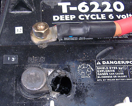
Last year when I was a green EV-er I just thought it was OK to connect all my cables to the battery terminals without checking them or even cleaning the oxide off the lead. Everything was OK – for a while. Then there was a pop and a fizzle on day and one of my terminals had melted and dropped molten lead onto the battery plates below. I was barely able to make it home and had to spend some time patching the hole in the battery and fishing bits of lead out.
I have been thinking ever since about some sort of device which will give me early warning about either weak cells and/or weak connections, that is, a high resistance link somewhere in my 16 long battery string.
Each of my batteries at rest is supposed to be at 6V (about 6.37V and a bit of fluff on top if they are fully charged). Under load they will “sag” because of their internal resistance down to, for my car under load, about 5V. If there is a weak battery, it will sag faster and lower than it’s friends. If there is a weak connection between the batteries, it will also cause a “sag” and heat up.
Some people connect a voltmeter to each of their batteries so that they can watch the condition of each battery from the cabin. I actually wanted a much more immediate kind of warning which involves a light lighting up when each battery and it’s next connection sag under load. 16 lights in all.
If the light was to light at about 5.5V, all lights should be out when the battery is unloaded showing that their resting voltage is good. Any light now would show up an uncharged battery. When applying load, all the lights should come on at about the same time, showing that all those batteries are stressed to the same level. One light on early or staying on for a while after the others spells trouble.

Here’s the circuit. It has two potential dividers using 3.3V Zener diodes and 100 ohm resistors and an LED between them This gives you two reference points, one 3.3V above the battery negative, one 3.3V below the battery positive. The difference between these is the sag from 6.6V. When the battery is at 6.3V it means that there will be 0.3V across the LED. Not enough to light it up. When the battery is busy and at 5V there will be 1.6V across the LED. that’s bright light! There are sixteen of these circuits (click on the diagram), one for each battery.
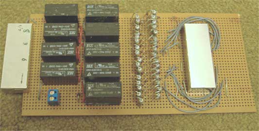
I have opted to disconnect my battery monitor from the batteries using lots of 12V relays. It’s crude but I don’t want my batteries drained by the monitor. The relay is controlled by the ignition signal and by another switch so that the monitor is only on when the ignition is on and the other switch is on.
The battery monitor is wired into the car using CAT5 ethernet cables. They are rated to take the kind of voltages and currently involved. Each wire has a 250mA slow blow fuse near the battery. At the moment only 10 of the 16 batteries are connected up.
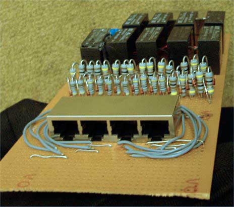
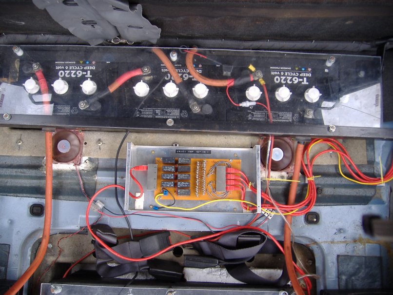
On the picture here you can see how I have used 2 banks of 4 RJ45 sockets to connect to the batteries and to connect to a smaller board with 16 orange LEDs on it for the display.
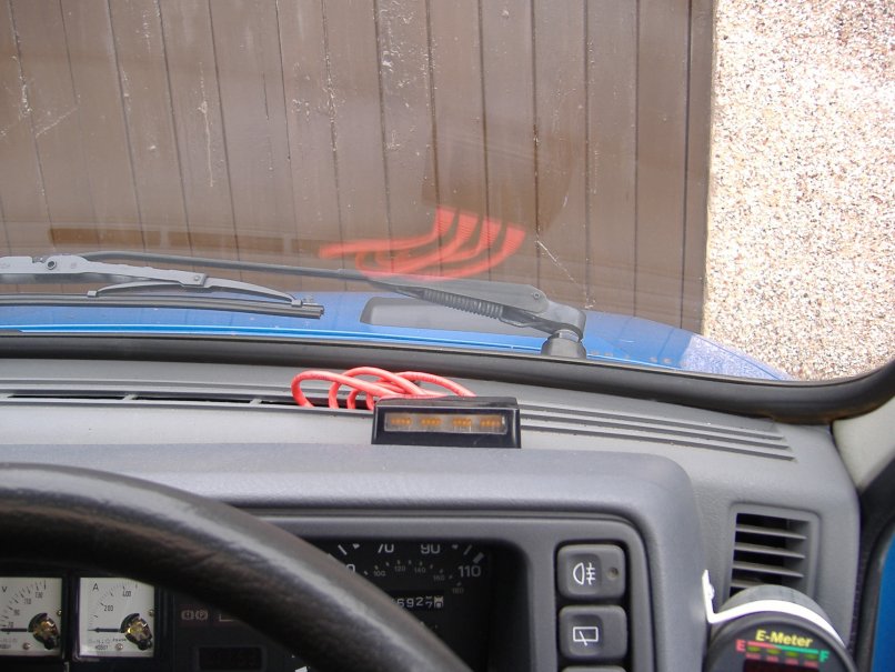
When the accelerator is pressed the orange LEDs on the dashboard display light up.
Here’s what it looks like installed in the car:
Now to see what improvements everybody can make to this design!
 James May in the UK

I recognize that circuit! :-) I posted it on the EV Discussion list a while back. Glad it worked out for you.
3.3v zeners are pretty poor. LM431s (with 2 resistors on one) would work better. The 100 ohm resistors could then be much higher values, so you wouldn’t need the relays.
CAT5 cable is not rated for the kind of voltage you will get between wires if directly connected to the batteries. It also burns. If you ever have a short in that cable, there had better be good high-voltage DC rated fuses between it and the batteries!
Hi Lee,
Thanks for your input!
I came up with this circuit independently a few months ago. Jerry told me that there were similar circuits out there.
The idea of replacing the zener diodes with something better is a good one. I think maybe a zener diode coupled with a transistor or maybe even better an op-amp. This would lower the current through it and sharpen the response. What worries me about using the LM431 is that, presumably, you’d need to trim all 16 circuits in to get exactly the same reference voltage as the resistors you’d be using for the potential divider on the LM431 could each vary by a few percent. For this circuit the reference voltages have to be very similar. Can you get around this?
What I am finding in practice is that the LEDs light up different amounts when the pack needs equalising. I’d lose this feature if the reference voltages vary by much.There are 250mA fuses on all the wires close to the batteries. I wouldn’t risk it without them. Maybe you are right about the CAT5 cable. No individual cable has more than 42V between any of its wires.
It would be nice to decouple this circuit with optocouplers for safety.
Maybe there’s a way to scan all the voltages. That way you can use just one circuit to measure and it won’t have to be matched.
Wouldn’t a simple PIC uController with a 16 channel A/D converter and 16 bit output to drive the LEDs give you more control?
You could program the uController to light the LED based on voltage differential instead of absolute voltages.
Inputs to an A/D would be extremely low current so there is no need for relays.
If that CAT5 cable does burn, you could end up in a whole lot of trouble. Its coating is very toxic when it burns, if you change nothing else, swap out that stock CAT5 for Plenum CAT5 which is will not give off the toxic fumes.
OK Guys I won’t use CAT5 next time!
Brian. The PIC sounds like a good idea. I haven’t used them before though. presumably all of the 6V signals in series would have to be decoupled somehow.
Regarding the LM431:
As long as you use 1% or better resistors there should be no need to trim the individual circuits.
-Peter
....and maybe get them all at once so they are the same batch.
I have just seen a nice looking bar graph battery monitor on evalbum
using an LM3914 LED bar graph display driver
I have dropped the owner an email. Maybe he’ll give us more info.
Looks great and I think I’ll copy it.
Nice job, James and thanks again for posting this and pitching in while I’m away.
Always great to see the different approaches to monitoring.
Before my Civic conversion went down with battery problems I was working on installing a touchscreen PC. I was hoping to be able to data log the output from my E-meter and to display all the info at once instead of having to select which one to view. I had also hoped to link to the speedometer pulse signal to work out watt-hours per mile range remaining in miles and so forth. For individual battery monitoring, might it be possible to use one of those parallel port setups to read each battery and feed the data to the computer as well? Anyone else look into this?
Hi Mike. I think I’ve seen your can on evalbum
Well, the wiring is in the car now, so I could upgrade to a small PC, or maybe even a PDA. There’s always the parallel to USB option as well, I believe you can get adaptors. Fortunately I have an e-meter, unfortunately no serial port on it. My Speedo is mechanical as well.
I don’t know what’s the best upgrade option for my monitoring system. It might have to wait. .. currently my thoughts are in aeromods ..like Darin (see this week’s links) and a controller bypass circuit.
car … not can!
I knew I recognised “Mike Chancey” It’s that crazy pusher-trailer on the page next to mine. I showed it to my friend who was seriously impressed. We concluded it was only legal because no law-maker had imagined it in their wildest dreams. So cool! I wouldn’t have the nerve.
We haven’t been able to figure out why, but some states actually define trailers as powered or unpowered. I am not sure what they mean by a powered trailer, but I suspect this isn’t it. Back to the PC idea, the speedo on my Civic is mechanical as well, but it includes a pulse generator to support the cruise control. I suppose one could use one of those magnet and coil sensor they aftermarket cruise units use. The real question is what ind of cose will it take to relate the E-meter data to the pulse frequencey (speed) and count (distance).
Oops! “ind of cose” should have been “kind of code”.
well the best way to write code like this would be to set up a simulator program on a PC which provides a similar data stream to what you’d get from the e-meter and the speedo pulse. Then you can develop to code an you can test all conditions by changing the simulator. It might not be too difficult to write the code. I’d probably use a j2me (Java micro edition) application on a hand-held computer, because that’s what I would understand. Anyway if you only take readings from the e-meter, you won’t see differences between you batteries, which I think is vital.
Hello everyone.
I am now prototyping battery-undervoltage-warning-circuit mark II based on the LM3914 bar display driver mentioned above. My prototype circuit seems good and on the strength of that I have ordered some of the parts I need to make the other 15 circuits. They’ll all have to be calibrated so that they all read the same number of segments at a certain voltage. I am currently using an old PC switched mode power supply. The 5V is (a bit )adjustable on this and at least gives me some of the bottom end range I need for calibration. I can get the top end by connecting between the 5V and 12 supply and adjusting the nominal 7V down. If I see a cheap adjustable bench supply I ‘ll be pleased though.
Hi everyone. I’m new to the world of conversion and had come across this site which has a lot of useful info. Thanks for having all this info available!
I was wondering if James ever completed the battery low voltage circuits and how did it turn out? Any schematics or instructions available?
Hi
James did complete it and it worked out OK!
It was a fairly good indicator of battery strain and whether your battery pack needs equalisation.
But…
I have a much better version now which uses 10 LEDs in a bargraph per battery. The lowest LED lights at 5.75V and the highest lit by 6.37V. (There is also a 12V version) You can trim each circuit in with a screwdriver. The effect is like a graphic equaliser and any light out of line indicates a possible battery or connection problem. I will write it all up soon on this site with schematics.- I really should have done it already. It is based on an LM3914 bargraph display driver chip. I have mounted them on strip boards in a very small form factor so they can be stacked together.
Of course, as everybody was politely trying to tell me, the CAT5 cables I have used throughout the car are really not good enough. There’s a substantial voltage drop and a smearing of all the readings due to the resistance of the wire interacting with the resistance of the meters. For it all to work really well, I am going to have to use larger wires.
How about something simpler for those of us that have monitoring already, just an alarm contact closure. I have a 5 battery moped, I want to have an alarm go off when I hit low voltage on any individual battery, not the string. The voltage would be the same for all batteries but I would want to adjust it with a pot from 10 to 11.85 volts if possible. The design does not need the alarm itself, but would need at least contact closure then the user could decide what the contacts trigger.
Hi Tracy
Yes, I think your idea sounds very useful. you would be able to back off on your moped when you know your weakest battery is in trouble. That’s what I used the above monitor for. You would also have a good idea which battery to charge individually to keep your pack in step.
Have you seen the later 10 LED monitor on this website? it might give you some more ideas, for example 10 different voltage thresholds which you could connect your alarm relay to.
I am currently using a paktrakr and a battery equaliser batteq and when I have more information about how they are holding up, I’ll write another article. So far looks promising. My old pack is recovering a little.
I’d like to know how you get on. At least you have 5 batteries and not 16!
I use a similar circuit with 50 volt zeners, and 10K resistors. The LED is replaced with a zero-center 25-0-25 volt meter. It now reads 75-100-125 volts, or, with a 100 volt system, directly in +/-%. It is not quite linear at the highest voltage, a volt or so off. I attempted some temperature compensation, but just ignore minor differences.
It works quite well on a 96 volt system.