

You will find articles organized by categories, along with recent comments, along the right hand column of the website. If you are just getting started with the idea of converting a gas car to electric be sure to check out Your First Electric Car
Welcome and enjoy!
-Jerry
Bring on the Heat · 2 December 05
There’s a number of things you need to do inside the electric car’s dash compartment. What that consists of depends on your donor car and the type of “stuff” you’ve decided to install in your EV.
First off there’s metering, which, ideally, would be in a visible spot. Either mounted on top of the dash (clunky and maybe unsafe if high voltage wires present) or somewhere in the instrument panel.
Our first EV had the meter installed down around the light dimmer switch, which meant that eyes were taken off of the road to read it. Not this time.
The other major dash item is the heater. Let’s talk about that and share a few pictures.
You have a few choices for heating an EV. The easiest choice, for the folks in southern climates, is no heater. Wouldn’t that be nice!
Some electric cars have propane heaters, which seems like a step backwards. Sure, there’s a lot more heat available, but now you have to “gas up” the EV from time to time.
Most folks opt for an electric heater. A newer model that I’ve seen is like an on-demand water heater that is hooked to the car’s old heater core and heats antifreeze. There’s a lag time of a few minutes as the liquid is warmed up and circulated.
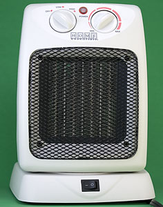
I’m using an electric ceramic heater, in fact two of them this time. Ceramic heaters can be picked up at a nearby hardware or *mart store for around twenty bucks. The model I picked up this year was slightly more expensive at $24 because it “oscillates.” Woo!
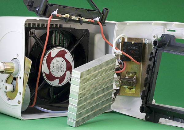
Here’s the rough layout inside as I started taking it apart.
Lots of screws. At least thirty of them.
The base is held on by four screws and inside is a C ring holding the pivot pipe to the base, since it’s the oscillation point. Once you pop the base off there’s another dozen screws to remove before the plastic case will open up.
Be a little careful and don’t force things. We don’t want to damage the surprise, prize inside.
For twenty four bucks there’s an incredible amount of parts inside.
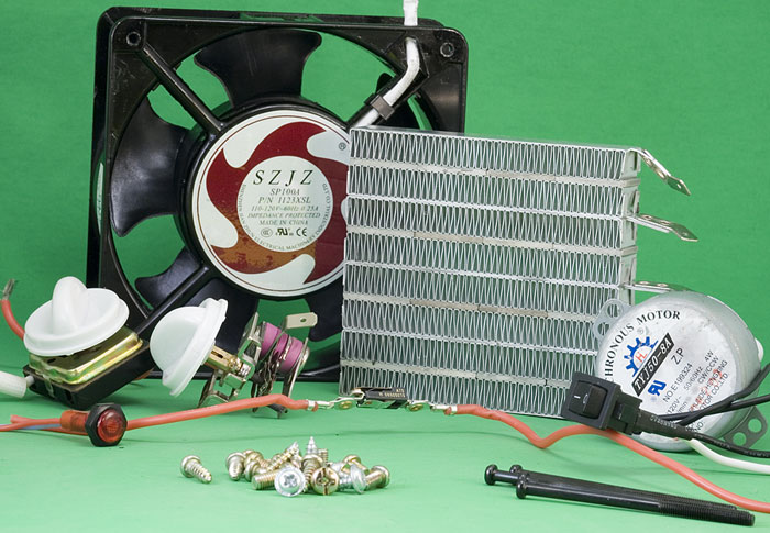
There’s a beefy muffin fan. As it turns out we need a couple of these to circulate air from our pellet stove and this should fit the bill.
There’s 30+ screws and bolts, a nice on/off switch, a multi-position switch, a variable thermostat switch, an AC lamp, and a small geared motor used for oscillating.
Right in the middle, with red wire leads, is the thermal cut-off switch. If you look at the previous image you can see it mounted in the black plastic. This interrupts power if the unit gets too hot.
And then there’s the star of the show, the Ceramic Heater Core.
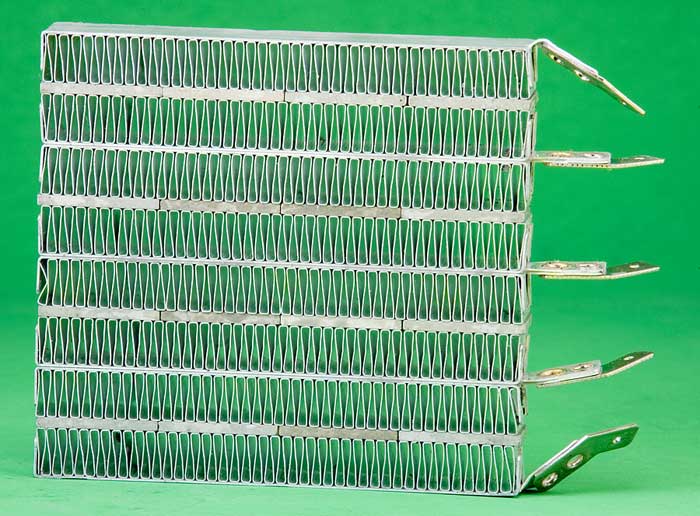
The way these things work is that voltage is applied to the metal leads. The leads and the squiggly radiator metal that looks like xmas hard candy conducts electricity to the thin ceramic wafers.
Zoom in on the picture and you’ll see four layers of ceramic material. When voltage is applied this heats up and the metal draws the heat away. Air flowing through the metal fins is heated up and blown into the house…or passenger compartment.
The beauty of the ceramic heater is that is has inverse resistance. Resistance is like pinching a garden hose and holding back the flow of water. In electronics it limits how much current flows.
The more current flowing through our ceramic heater the warmer it gets. But since this has inverse resistance the ceramic’s resistance goes up as it gets hotter. More resistance means less current flow and heat output goes down. It’s still hot, mind you, but somewhat under control.
Blowing air through the fins draws away the heat, resistance goes down and heat production goes up. Wonderful science!
Now to figure out where to put all of this wondrous heat.
I have two choices: try to cram it into the original heater core position or into the box where the AC core used to be.
The heater in your car looks alot like the ceramic heater core, but instead of layers of ceramic it has tubing to route the hot radiator liquid through. In fact all of the time, Summer and Winter, there’s hot radiator fluid running behind your dash.
Well, that’s not always true. I’ve see cars with a flow control knob, but Eve didn’t have one.
One of my old junker cars had a radiator problem (radiator thermostat stuck closed) and the short term kludge was to drive around with the heater running full blast…in the Summer!
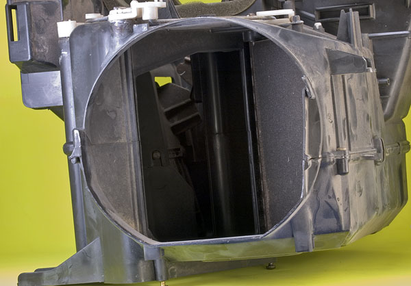
How do they keep you from getting cooked by all of this heat? Well, there’s a big ol’ flap that diverts air. The photo above shows the air circulation/heating chamber as viewed from the incoming air’s perspective. When you move the heat lever you are really opening up a flap and directing some of the incoming air through the heater core. Close the flap and the air goes another route. No heat.
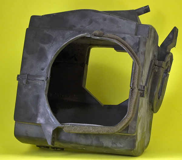
It’s kind of cramp in that box and, to be quite honest (and safe!), we don’t want the ability to reduce air flow to the ceramic heater. A better location is inside the A/C core box shown here.
My plan is to use the ceramic heater’s original black plastic (which seems to be some type of heat resistant substance) and connect the two ceramic cores back to back, with a couple of inches between them. This will be mounted inside the box such that all air has to flow through the heaters.
As a reminder, here’s the heater schematic:
The first EV used the air conditioning on/off switch since it was in the right place and not being used. Probably do the same thing here. What might be interesting is to combine that with the variable thermostat that came with the heater: when a certain temperature is reached the relay is turned off.
Speaking of relays the schematic shows two of them. The first one turns on the big relay, supplying 144vdc to the heaters. It also grounds the fan.
The blower fan in a car works at different speeds by changing the amount of resistance between the motor and ground. On LOW there’s three resistors, on MEDIUM two, HIGH has one, and on MAX no resistors.
The resistors are kind of interesting. They are big rolled up wires mounted inside the blower fan box. Since they have to deal with a lot of current going through them they get hot, so they are placed in the path of the blowing air.
Yet another source of heat when running the fan in the Summer!

How di dyou learn all of this electrical stuff
Hi Ed,
I’ve picked up a bit on my own over the years. Also some electronics training in the Air Force and FAA.
And from Bob.
But that’s another story…
I use a small “milkhouse” type electric (110 volt)heater while I do chores in the morning (1/2 hr), then take it out and go to town. The heat in the car goes through the defroster and keeps the w/s clear for the 5 mile trip to work. Then I put it in the shop until the trip home at noon. If the sun is out, it will keep the car warm until I go back to work and then back into the shop. The only time I need the heater is in the morning.
I didn’t read it all word for word but I assume this is a 120 volt AC ceramic heater as the donor ?
You didn’t read it all?? Oh, man…
”:^)
Yep, ceramic heater.
Milkhouse heaters, if I remember correctly use a long heated wire strung between ceramic insulators. Fan somewhere behind.
Those aren’t as good for putting behind the dash since they aren’t self regulating. Lose the fan and the wire would most likely melt down.
I used the wire from one of those “wire” heaters to make battery boxes for the first EV. Attached to a Variac (variable AC transformer) I could selectively heat up plastic and bend it.
I see… AC heater as the donor.
This is really useful to me as I’m about to build my heater system. I particularly like the wiring which keeps the fan on at least setting 1 when the heater is on. My Haynes Manual shows that my fan wiring is similar to yours so I can copy your setup. Unfortunately, i may have trouble finding a 120vac heater in the UK as we run on 240V. My car is 96 V nominal. I think my EV supplier can get one though!
hello,
i understand that whichever current is applied, the heater will self limit its heat output ?
if so what is the peak temperature ?
i guess it is designed not to melt its own casing ;)
hi Minhloc.
The resitance of the heater wire is dependent on temperature. The resistance increases with temperature limiting the current. It will end up a little bit higher temperature on a higher voltage supply, but it it still self-limiting.
Does the voltage ‘rating’ of the heater core even matter? I have taken a ceramic core from a 1.2kW, 240V appliance (looks very similar to the one on Jerrys webpage) and applied a 218VDC supply from bridge rectified mains (240AC). I got a max temp of around 536C with no fan. A 12V fan brought that down to 464F and running the same fan at 9V gave me 496F.
I tried it again with a 110VAC transformer and rectifier but the temperature barely got to 100F. I suspect that I was not able to pull enough amps through my little transformer. Simplistically speaking, given that V=IR and that R is fixed by the heater element, wouldn’t I have needed to pull twice the amps at half the volts for the same temperature (power draw)? I may try this again with a half bridge recitifier straight off the mains.
I am hoping that a 144V battery pack can provide more than adequate amps to run the element otherwise I have wasted 40 bucks on what used to be a perfectly good heater.
Hi Nick
Is it worth measuring the voltage across your element while it is connected to the 110 transformer?
I suspect that if the transformer isn’t very big, it’s internal resistance will cause a large voltage sag and you won’t be getting nearly 110V across your heater element. This won’t be problem with your battery pack which will have an internal resistance in the milliohms range. After all that is said, my 120V heater element isn’t very hot on 96V, though it does work. The resistance of the heater element isn’t very fixed, it goes up with temperature, so you’ll probably get more than half of the power output running it on 144V, because the it’ll run a bit cooler and it’s resistance will be lower.Another way to tell is run two in series from the mains to get 120VAC. it’s another 40 bucks though!
Hi James
I tried out the heater element again with a half bridge rectifier. It didn’t occur to me until after I bought a diode that I could use the bridge rectifier I already had by connecting the +ve 240AC to one terminal and taking it out of the DC+ve terminal, thereby using only one diode in the bridge. I could have done this experiment months ago I had really been thinking – doh!
Anyway – I got 107 VDC out of it and when I fired it up I got a max reading of 252C (484F). The thermal trip kicked in at 246C but I bypassed this for the tests. I will definitely use it in the car and also have the fan running as per Jerrys heater schematics.
Putting the 12v fan on it dragged the temp down to 165C. Running the fan at 5V and 6.6V resulted in 202C and 181C respectively. I tried 9V but the power supply keeps tripping (I made a bench supply from a computer power supply using instructions from one of Jerrys links).
I live in Auckland, New Zealand, so don’t need much heat (it never freezes) so I would conclude that the “240V” heater element will do the job for me. If someone needed more heat I think that a couple these in parallel would do quite nicely. I will have to let someone else figure out what effect that has on the total resistance, current draw and heat output.
One word of advice – don’t touch the heater elements! Obviously they are hot but I also got a jolt off it – the first of many no doubt!
Hi Nick
Yes I have learned about electricity too. Now I wait a long while after use before opening a TV. Glad you’re happy now. Don’t expect the performance you are used to from a car heater.
Could you shroud the drive motor and suck heat off of that? I saw a citicar the other day: seemed like that’s what they did for heat.
I’ve heard of folks who have tried this. From what I remember you don’t get all that much heat but you do get a lot of smell from it.
Has anyone had any luck installing a Chrysler GEM heater in a Beetle EV. I know they run on a 72v system which is what I am building. If the GEM heater will work, then it might save me a lot of modification time.
Folks: You can use an electric flash boiler that is available to warm antifreeze. They are available for over the road trucks with sleepers to keep them warm in the winter. Simple hookup, “NO” rewireing.
Inventor.